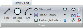
Draw / Edit
Click for complete
Draw
menu documentation.
Users may customize
the Ribbon Interface by changing icon style and placement.
|

|
Moving the cursor over
an icon will activate it as in the image here.
Click
the icon to select that function, and then move the cursor into
the AP100US
work area (onto the part or sheet) to execute the operation.
Note: All icons function in the same
manner.
|
|
The Draw>Line flyout menu includes:
Line,
Multiple Lines, Rectangle Lines
and Rounded Corner Lines.
|
Click
the drop-down arrow to reveal the flyout menu as in the image
to the left.
Select
an option, such as Multiple Lines, and the icon will then
illustrate that choice, as shown here - |

|
Now
move the cursor directly into the work area to draw multiple lines.
(The Multiple
Lines icon will remain until another line type is chosen.)
|
| Click
for more info on drawing
Lines, Multiple
Lines, Rectangle Lines and
Rounded Corner Lines. |
|
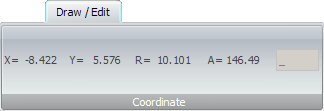
After
an option is selected
and
the cursor is moved into
the
work area, the current
ribbon
will display cursor coordinates instead of icons.
See
Coordinates for more info.
Note:
Not available for all options. |

|
Notice
that some functions, such as Round Hole, have no flyout menu.
See
Round Hole for more info. |
|
| |
|
|
|
|
|
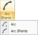
The
Arc flyout menu also contains the Arc 3Points function.
See
Arc and Arc 3
Points for more info. |

|
Click for
more
info on drawing an obround. |

|
The Shape
Library allows the user to choose and edit pre-set shapes and
groups of shapes.
Click
for more
info on the Shape Library. |
|
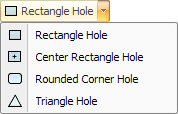
The
Rectangle Hole flyout menu also contains the Center Rectangle,
Rounded Corner and Triangle Hole functions.
See
more info on drawing Rectangle,
Center Rectangle, Rounded
Corner and Triangle holes.
|
|
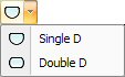
The Single
D flyout menu also contains the Double D function.
See
more info on drawing Single and Double D’s.
|

|
Points provide
anchors and additional dimensions for complex drawings.
Click
for more
info on inserting a point. |
|
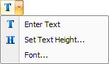
The
Enter Text flyout menu also contains the Set Text Height and Font
functions.
Click
for more
info on text options.
|

|
Click for
more
info on drawing an ellipse. |

|
Select to
open the Notch Library option, which allows users to apply notch
patterns to intersecting lines that comprise part boundaries.
Click for more
info on notching. |

|
Click for
more
info on drawing a radius slot. |

|
The Placing
Tool Hit option places patterns that match the tools in your inventory.
Click
for more
info on placing tool hits.
|

|
The Add
Flange option is useful for developing a flat pattern from a drawing
of a formed part.
Click
for more
info on adding flanges. |

|
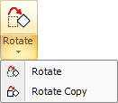
This option
allows you to rotate a part.
Click
for more Rotate Part
info. |

|
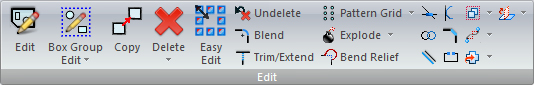
The options
on the Edit menu allow you to correct individual patterns, process
geometry and manipulate groups of patterns.
Click
for Edit Patterns
menu documentation.
|
|
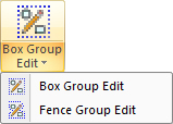
Select
an option from Box Group Edit to edit pattern groups.
Click
for more info on Box Group Editing. |

|
The
Copy Patterns option allows you to replicate a pattern.
Click
for more info on Copy Patterns.
|
|
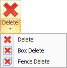
The
Box Delete option on the Delete Patterns submenu allows you to
draw a rectangular box, or marquee, around several patterns.
Click
for more info on Deleting Patterns.
|

|
Easy Edit
makes editing patterns easier by allowing patterns in parts to
be edited with simple mouse-clicks.
Click
for more info on Easy Edit.
|

|
The Undelete
Pattern option restores the last pattern that you erased using
any of the Delete Patterns options.
Click
for more Undelete Pattern info.
|

|
The Blend
Patterns command allows you to place an arc between any two lines,
arcs or rounds, or any combination of any of these two pattern
types.
Click
for more Blend Patterns info.
|

|
The Trim/Extend
command can extend one line to another line, or shorten one line
to stop at an intersection.
Click
for more Trim and Extend info.
|
|
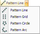
These group
patterns consist of copied entities that are replicated in some
type of grid pattern.
Click
for more Pattern Line, Pattern
Grid, Pattern Circle &
Pattern Arc info.
|
|
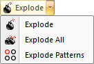
The Explode
options allow you to divide grouped entities into individual patterns
or to split a single entity into multiple entities.
Click
for more Exploding and Splitting
Patterns info.
|

|
Primarily
used to prevent the formation of sharp tabs during the bending
process, the Round Line Corner option allows the user to
apply a round radius to the inside of a corner. The lines are
trimmed to the ends of the radius and the system will assign the
designated relief tool to that pattern when you tool the part
or sheet.
Click
for more Bend Relief info.
|

|
Use Intersect
Patterns to calculate the intersections of lines, arcs, rounds,
or a combination of these patterns.
Click
for more Intersect Patterns
info.
|

|
Join patterns
by placing a tangent line between two arcs or rounds, making the
line tangent to either side of the arc or round.
Click
for more Join Patterns
info.
|

|
Create a
line that is parallel to any line on the part using the Parallel
Line option.
Click
for more Parallel Lines
info.
|

|
This option
locates tangent points from any point on a part or sheet to a
line, arc or round.
Click
for more Tangent Patterns
info.
|

|
Place a
chamfer on any corner or intersection using the Chamfer Line option.
Click
for more Chamfer Lines
info.
|

|
This option
allows you to divide grouped entities into individual patterns
or to split a single entity into multiple entities.
Click
for more Splitting Patterns
info.
|
|
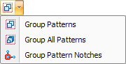
These options
allow you to group lines, arcs and notches into standard patterns.
Click
for more Group Pattern Options
info.
|
|
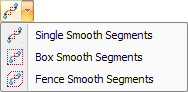
These
options allow you to select a single polygon segment, or multiple
polygon segments, and “smooth” or reduce the number of patterns
to create arc patterns.
Click
for more Smooth Segments
info.
|
|
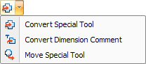
These options
allow you to convert special tool patterns into standard patterns,
convert comments into special tool patterns and move grouped patterns
that comprise special tools to a new location.
Click
for more Convert Options
info.
|
|
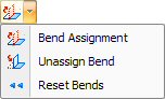
These options
allow you to apply bend parameters to the construction lines of
a part, thereby producing a three-dimensional bend model that
you can use in a bending report.
Click
for more Part Bending Options
info.
|
|
|

|
Click to
define a macro.
Click
for more Define Macro info. |

|
Set Origin
allows you to change the origin for a macro.
Click
for more Set Origin info.
|

|
The Copy
option allows you to duplicate an entire macro anywhere within
the work area.
Click
for more Copy Macro info.
|

|
The Move
option allows you to relocate a macro to any location within the
work area.
Click
for more Move Macro info.
|

|
The Mirror
option creates a mirror image of the macro.
Click
for more Mirror Macro info.
|
|
The Rotate
option allows you to rotate patterns defined as a macro around
the macro origin at any angle. Click for more Rotate
Macro info.
The
Rotate Copy command allows you to duplicate and rotate macro patterns
around the macro origin.
Click
for more Rotate
Macro Copy info.
|
|
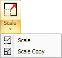
The Scale
Macro option allows you to modify the size of a macro by specifying
a ratio. Click for more Scale
Macro info.
The
Scale Copy option creates and scales a copy of the macro; the
original macro remains unchanged.
Click
for more Scale
Macro Copy info.
|

|
The Add
Pattern option on the Macro menu allows you to add patterns to
an existing macro.
Click
for more Add
/ Remove Pattern info.
|

|
If you modify
the part size, you can use the Redefine Part option to recalculate
the size.
Click
for more Redefine Part info.
|

|
The Remove
Pattern option on the Macro menu allows you to remove patterns
from an existing macro.
Click
for more Add
/ Remove Pattern info.
|

|
The Flip
option allows you to reverse the macro patterns in relation to
their origin.
Click
for more Flip Macro info.
|


|
The Delete
option on the Macro menu allows you to erase a macro.
The
Undelete option on the Macro menu restores the last macro pattern
you erased as an entire group using the Delete command.
Click
for more Delete / Undelete Macro
info. |