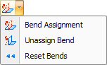
Bend Assignment
The Bend Assignment option in the Part Bending submenu allows you to assign bend properties to construction lines. Select the option from the submenu and move into the work area. As you click the construction lines, the system updates the flange definitions and displays the three-dimensional model in the 3D Bend Representation window. The command will remain active until you select a different option. |
Unassign Bend
The Unassign Bend option in the Part Bending submenu allows you to remove a bend assignment. When you select this option, and then select a construction line having bend properties, the entry is removed from the table. The system will update the flange definitions in the 3D-Bend Representation window. The command will remain active until you select a different option. |
Reset Bends
The Reset Bends option on the Part Bending submenu will remove all the bend properties. The system will prompt you to confirm. Click OK to reset the bend lines or click Cancel to preserve the current bend information. |
Bending Properties |
The options on the Part Bending submenu allow you to apply bend parameters to the construction lines of a part, thereby producing a three-dimensional bend model that you can use in a bending report. When bend properties have been entered for a bend line (such as Order 1), the next bend line selected in the work area will automatically have the same bend properties (Order 2). Select and enter values manually for an individual row, or multi-select more than one row and right-click to display the flyout menu, which enables the user to enter properties for all selected rows. |
|
Flange The Flange Length is derived from the pattern length(s) adjacent to the bend line. You cannot edit the values that appear in the Flange column of the table. |
Bending Type Select one of the bending types available. V-Air (Air Bending) is done with the punch touching the workpiece, but not bottoming in the lower cavity of the die. V-Coining (also called Bottoming) is the bending process where the punch and the workpiece bottom on the die. |
V Width This is the size of the "V" opening of the die. Select a V Width from the drop-down (the options available in the list are the tools in the inventory). |
Angle The Bending Angle allows you to set the actual flange angle relative to the remainder of the model. The angle is calculated from the moving angle relative to the flat surface of the material. |
Radius The Bend Radius allows you to note the radius of the bend for the purpose of report creation. The value that you type in the field does not affect the bend model. |
Deduction The Bend Deduction allows you to note the deduction for the purpose of report creation. The value that you type in the field does not affect the bend model. |
Type The Type field allows you to set the direction of the bend. Double-clicking a field in the Type column toggles between “Front” and “Back”. |
Order The Order field indicates the selection order. The first bend you select becomes bend “1”, the second bend, bend “2”, etc.
|
Notes: You can only select construction lines for bend assignments. If you select a solid line, the system will ask if you want to convert the line type to construction.
|
The end points of the construction lines must connect to the part boundaries. |
