![]()
You can create a line that is parallel to (or offset from) any line on the part using the Parallel Line/Offset option. You can create a parallel or offset line through a point or from a specified distance from the original line. |
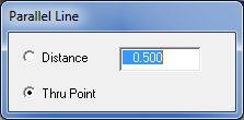
When you select Parallel Line from the submenu, the Parallel Line dialog opens. If you want to specify the spacing between the original line and the new parallel line(s), select Distance and type a value in the text box. If you want to run the parallel line through a point, then select the Thru Point option in the Parallel Line window. |
|
Example 1: Parallel Line(s) using Distance |
Create a new 10 x 10 part. Draw a vertical line with a start point of 2X 2Y, and an end point of 2X 8Y. |
Select Parallel Line and move the pointer into the window. If necessary, select Distance and the current value in the text box to the right. Type .25 <Enter> to specify a distance of 0.250. |
Move the pointer into the work area and click the vertical line. The system prompts you to select a placement for the line. Move the pointer slightly to the right and click. A second line appears that is 0.250 from the original line. Click the second line, and then move the pointer slightly to the right and click again. A third line appears that is 0.250 from the second line. See the illustration below: |
|
|
Example 2: Parallel Lines using Thru Point
|
|
Draw a new vertical line on the part having a start point of 3X 3Y, and an end point of 6X 7Y. Select Parallel Line. Move the pointer into the window and select Thru Point. |
|
|
|
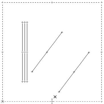
Move the pointer into the work area and click the fourth line. The system prompts you to select the placement for the line. Move the pointer to the lower edge of the part and right click to snap. |
|
Now click the left mouse button. A fifth line appears. Notice that if the line were to continue, it would bisect the lower construction line and pass through the snap point. See the illustration below: |
|
|