![]()
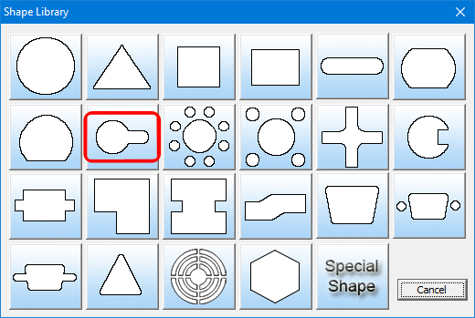
The Shape Library supports 22 standard shapes and a special shape. Create an entirely new shape or edit an existing shape, and place the shape on a part in various patterns.
To create a new shape such as KeyHole (circled in red), click on the KeyHole shape to open the Design / Edit Shape window. (If a previously saved Keyhole shape already exists, selecting KeyHole will open the Shape Placement window.)
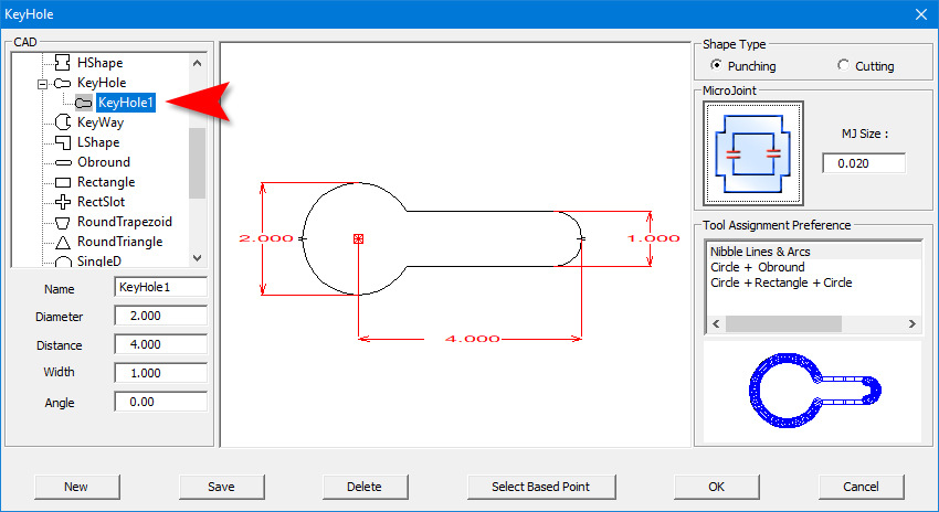
Clicking Keyhole in the Shape Library opens the Design / Edit Shape window. Notice that a new KeyHole1 has been created and is listed in the CAD Shape gallery. Now it is necessary to enter values for the new shape and save it before it can be placed on a part or a sheet.
Note: Although KeyHole1 is the active shape, any other shape in the CAD Shape Gallery may be selected at this point. If a different shape is chosen, the system will prompt the user to save or delete the KeyHole1 shape. (Options here vary according to shape type.)
Name
Enter any unique name for the new shape, or keep the name created by the
program (such as “KeyHole1”). Confirm the new name and advance to the
next field by hitting <tab>.
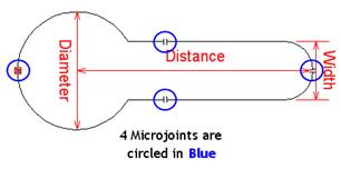
Diameter
Enter the Diameter in inches for the new shape. The range is 0.001~1000000.
Hit <tab> to confirm the new value and move ahead to the next field.
Distance
Enter the Distance in inches for the new shape. The range is 0.001~1000000
and hit
<tab> to confirm the new value and move ahead to the next field.
Note: The system will reject user-entered values, which prove to be incalculable. In such a case, an incorrect user-entered value will remain in the field, but when the user tabs down to the next field, the Shape Preview will remain unchanged.
Width
Enter the Width in inches for the new shape. The range is 0.001~1000000.
Hit <tab>
to confirm the new value and move ahead to the next field.
Angle
Enter the Angle in degrees for the new shape. The range is -180°~180°. Hit <tab> to confirm the new value.
Shape Preview
The Shape Preview in the center displays the shape illustration and microjoints
if they have been assigned. Roll the mouse wheel to scale the preview.
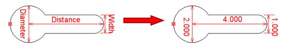
When the Preview display area is right-clicked, the Show Value flyout menu displays -
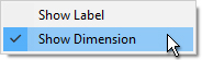
Choose Show Dimension and the names of the dimensions, such as “Distance” and “Width” display. Choose Show Number and the values of the dimensions, such as “2.000” and “4.000” display as in the illustration below.
Shape Type
Select Punching or Cutting as the Shape Type. One or the
other option may be disabled, depending upon the machine that is currently
loaded. If a combination machine is loaded, then both options are available,
as in the image.
(Note: The choice made here affects the options available in Preferences > Tooling.)
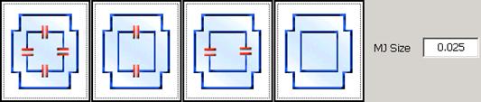
Microjoints
To place microjoints click the graphic to toggle through the four microjoint
assignments shown below. When any one of the first three assignments is
clicked, the MJ Size field becomes active and a default size of
0.025 is automatically entered in the field. Enter another microjoint
size as needed.
(Note: Default values for the microjoint size are from Preferences > Tooling or Preferences > Cutting.)
The first assignment places microjoints on all four sides; the second assignment places microjoints on the top and bottom; the third assignment places microjoints on the sides; assignment four places no microjoints and disables the MJ Size field.
When the first graphic is selected, the newly entered microjoint assignments display in the Preview as shown below.
See Preferences > Tooling for more information.
(For general information on Microjoints, please see Sequence Features>Punch Microjoint Options and Sequence Features>Cutting Microjoint Options.)
Tool Assignment Preference
The list box shows all the tool assignment preferences for the KeyHole
shape. Tool Assignment Preferences vary depending upon the shape
itself and the selected Shape Type (Punching or Cutting).
Select a Tool Assignment Preference in the list and the tool assignment preview of this shape is shown as a thumbnail image.
Note: If the ''Nibble Lines & Arcs" or "Line & Arc" tool assignment preference is selected, then the shape instance will be auto-converted to line and arc after placement.
The Tool Assignment Preferences with previews for the KeyHole shape when Punching is chosen as the Shape Type are as follows -
 |
 |
- Nibble Lines & Arcs - The machine nibbles out the lines and arcs. |
- Circle + Obround - The machine punches out the shape
|
 |
 |
- Circle + Rectangle + Circle - The machine punches out the shape with single-hit
Circle, Rectangle and Obround Tools. |
- Line & Arc - When Cutting is the Shape Type, |
Tools with Specific Tool Assignment Preferences -
When punching Circle, BoltHole, Square, Rectangle and Obround shapes, “No preference” is available in the Tool Assignment list. If this is selected, then no tool assignment preference will be saved with the shape. After the shape is placed (when auto-assigning tools) the program will refer to the global tool assignment setting in Preferences > Tool Assignment to assign tools to this shape type.
When punching Corner Radius, DoubleD and SingleD shapes, special single-hit tools are available in the Tool Assignment List.
When cutting Circle, Triangle, Square, Rectangle, Obround, DoubleD and SingleD shapes, “Single Pattern” is available in the Tool Assignment list. When this option is selected, the system will place a standard pattern (Round Hole if Circle is the current shape).
Command Buttons
New
Click New at any time to create a new shape based on the program’s
template of the currently selected shape. If New is clicked the system
prompts the user to save the current shape that is under construction.
Save
Click Save to save any changes while remaining in the Design Shape
Dialog Box.
Delete
Click Delete to delete the selected shape from the Shape Library.
Note: It is not possible to delete shape templates from the Shape Gallery. Only user-created shapes can be deleted.
Flyout Menu
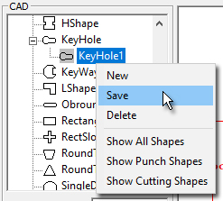 |
While in the Shape Gallery (or Shape Placement), right-click on any shape to display the flyout menu - New will create a new shape based on the highlighted shape. Save will save the highlighted user-created shape. Delete will delete the highlighted user-created shape. Choose Show All Shapes to show both Punch and Cutting shapes, or select Show Punch or Show Cutting to display just those shapes. Note: It is not possible to delete shape templates from the Shape Gallery. Only user-created shapes can be deleted. |
Select Based Point
If the Select Based Point button is clicked all available based
points for this shape will display in blue. When the cursor is moved into
the Shape Preview area and comes near a particular based point, then that
point will be highlighted in red.
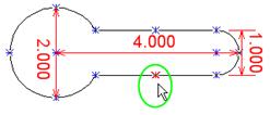
The selected based point and cursor are circled in green
By single-clicking the left button, this point will be chosen as the default based point of the shape. This selected based point will always display in the Preview.
If it becomes necessary to choose another Base Point while in the CADCAM work area, see Choosing another Based Point.
OK / Cancel
Click OK to save any changes and close the Design Shape Dialog Box. The
program returns to the Shape Placement window. Click Cancel to close the
window without saving any changes. The program returns to the Shape Placement
window.
The KeyHole shape, selected in the Shape Library window (above), remains highlighted in the Shape Gallery pane in the Shape Placement window.
Note: Any shape listed in the Shape Gallery may be selected at this point.
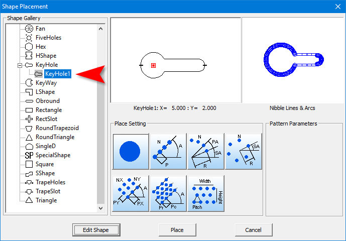
The Shape Placement Window information panel and Pattern Parameters are empty and the Place Setting buttons are inactive until a shape is created.
You must now create a new shape based on a shape template before you can proceed.
With a shape template (such
as KeyHole) selected, click the ![]() button to open the Design Shape Dialog box.
button to open the Design Shape Dialog box.
Note: To precisely position patterns try the Coordinates feature in the Draw menu.
Placing
a Shape on a Part
Placing a user-created shape must be done from the Shape Placement window.
If the program is in the Design Shape Dialog Box, save any changes and
click OK or Cancel to return
to the Shape Placement window.
Shape Gallery
The Shape Gallery displays any new user-created shape instances that are
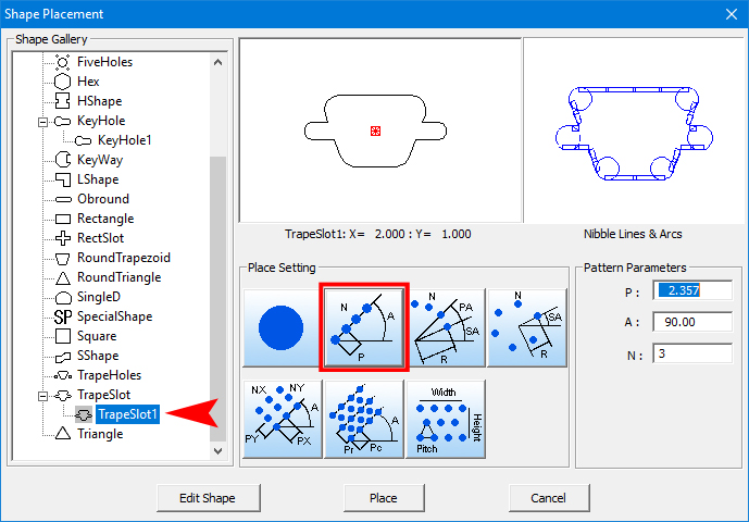
available in the library. When a shape name is clicked (such as TrapeSlot1),
the name will be highlighted. While in the Shape Gallery, right-click
on any user-created shape to display the flyout menu described above.
Thumbnail Preview
When a shape is selected, a thumbnail preview of that shape appears
showing basic values for the shape. At the right the preview of the referenced
tool assignment for the selected shape appears in blue.
Place Setting
Until a Place Setting is selected, the Pattern Parameters panel remains
empty.
Select one Place Setting to place the shape on the sheet or part. (This Place Setting will become the default for that particular shape type, and will remain so until changed.) The system then displays default Pattern Parameters for that pattern.
Note: When placing a grid for shape instance such as keyhole (not including the standard pattern), it will be auto-converted to a single pattern.
|
No parameters for single shape placement. When this option is chosen, the program will place a single instance of this shape on the part or sheet. Note: The Pattern Parameters panel is disabled for this option. |
|
|
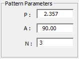
N – Number of shapes placed in the shape line. A – Angle in degrees between the shape line and the X- axis. P – Space between two shape patterns. Enter values in the Pattern Parameters fields for the placement of the pattern and hit <tab> to confirm the new value(s) and advance to the next field. Any new Pattern Parameter values entered are automatically saved by the program. |
|
|
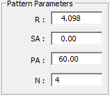
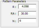
N – Number of shapes placed in the shape arc. PA – Step angle between two shape patterns. SA – Angle between the first shape in the shape arc and the X-axis. R – Distance between the center point of the shape arc and the snap point of the shape. Enter values in the Pattern Parameters fields for the placement of the pattern and hit <tab> to confirm the new value(s) and advance to the next field. Any new Pattern Parameter values entered are automatically saved by the program. |
|
|
N – Number of shapes placed in the shape arc. SA – Angle between the first shape in the shape arc and the X-axis. R – Distance between the center point of the shape arc and the snap point of the shape. Enter values in the Pattern Parameters fields for the placement of the pattern and hit <tab> to confirm the new value(s) and advance to the next field. Any new Pattern Parameter values entered are automatically saved by the program. |
|
|
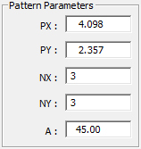
NX – Number of shapes placed in the grid in the X direction. NY – Number of shapes placed in the grid in the Y direction. A – Angle of the shape grid. PX – Space between two shapes in the X direction. PY – Space between two shapes in the Y direction. Enter values in the Pattern Parameters fields for the placement of the pattern and hit <tab> to confirm the new value(s) and advance to the next field. Any new Pattern Parameter values entered are automatically saved by the program. |
|
|
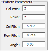
A (Angle) - Angle of the shape grid. Pc (Col Pitch) - Pitch or distance between columns. Pr (Row Pitch) - Pitch or distance between rows. Columns - Number of columns in the shape. Rows - Number of rows in the shape. Enter values in the Pattern Parameters fields for the placement of the pattern and hit <tab> to confirm the new value(s) and advance to the next field. Any new Pattern Parameter values entered are automatically saved by the program. |
|
|
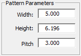
Width - Overall width of the shape. Height - Overall height of the shape. Pitch - Pitch or distance between shapes. Enter values in the Pattern Parameters fields for the placement of the pattern and hit <tab> to confirm the new value(s) and advance to the next field. Any new Pattern Parameter values entered are automatically saved by the program. |
|
Edit
Shape
Edit the selected shape by clicking the Edit Shape button to open the Design
Shape dialog box.
Place
After a
Place Setting Pattern Type has been chosen and values entered, click the
Place button to place the pattern on a part or sheet that is already
open in AP100US.
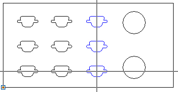
When Place is clicked, the shape placement dialog closes and the part or sheet mode is active. The shape to be placed is attached to the cursor (now a crosshair), which must be moved to the correct position on the part or sheet and then placed by left-clicking the mouse.
Enter coordinates (X/Y/A/R) in the output pane to place parts if desired. After the shape instance is placed, return to the Shape Placement window by hitting <shift> + <Esc> on the keyboard.
Cancel
Select to stop the current operation. Choosing Cancel will close the Shape
Library window altogether.
Choosing
Another Based Point
For a Single Shape, Shape Pattern Line or Pattern Grid.
After clicking the Place button in the Shape Placement Window, the shape placement dialog closes and the part or sheet mode is active. At this moment the default base point (or the user-selected base point) of the selected shape will be attached to the center of the crosshair.
To switch to another Based point, before left-clicking to place the shape, hit <ctrl> + F2, which locks the shape or pattern in place. Move the cursor around the shape or pattern and the nearest based point(s) will be highlighted.
Single left-click a different based point, which then becomes the new based point. The shape or pattern can be moved again based on the newly selected based point.
 |
 |
 |
Hitting <ctrl> + F2 locks the
|
Left-click select the |
Move the shape or pattern |
Snap Points
It is also possible to right-click to
snap the based point to any snap point of the other existing patterns
in the part or sheet. If the location is satisfactory, left click the
mouse to confirm the location. This finishes the placement.
Shape Pattern
Arc & Pattern Circle
When placing a Pattern Arc or Pattern Circle, choosing a different based
point of the arc or circle is permitted. The center point of the arc and
the circle is calculated according to the based point of the shape instance.
The illustrations below show 5 possible changes of the pattern arc circle.