Options on the Punch Microjoint submenu allow the user to auto-place, manually place, edit, delete, view and clear punching bridge microjoints.
You can place up to 100 bridge microjoints on each part or on sheet patterns. You must activate Part view before you can place punching microjoints. Bridge microjoints are saved with the part and sheet. You should place the microjoints before you assign tools. See Tool Assignment.
Additional options allow the user to Assign, Unassign, Clear or Inquire a Microjoint Tool.
Note: For parts that were either opened in work area in the standard way or were drawn using CAD features, it's best to apply/edit microjoints in Part View. However, if patterns were drawn directly on a sheet, it's best to use these microjoint functions in Sheet View. Still, approaches may vary according to user's particular machine/sheet/overall environment.
![]()
The Auto Microjoint option automatically places bridge and corner microjoints using the parameters specified in the Punching Microjoints panel of the Material Information window.
If your machine is equipped with a MJC (Micro Joint Cutter) device, you can choose whether to have the joints processed by the machine by clicking Yes in the dialog that displays.
If you click Yes, the joints will be cut by the MJC device. The system will determine the joint type (corner joint, bridge joint, special tool joint) and angle automatically. If you click No, the system will use the designated relief tool in the turret to cut the microjoints, or adjust the tools along the paths using the parameters in the Punching Microjoints panel to create the microjoints.
![]()
The Place Microjoint option on the Punch Microjoint submenu allows you to manually place bridge microjoints along the part boundaries, arcs, lines, C-notches and V-notches.
Notes:
You can define the default size for your bridge microjoints in the Punching panel of the Preferences window. Select Preferences from the File menu to display the Preferences window. Navigate to the Punching panel and type a new value in the Microjoint Size text box under Punching Feature Values.
You cannot use the right mouse button to snap. The right mouse button cancels adding microjoints along one path so you can select a different path.
You may find it convenient to define a step value and use the <Arrow> keys, or to type the location using X and Y coordinates.
You can place a corner microjoint by dragging the positioning marker to the vertices of a corner.
Select Place Microjoint and move into the work area. The pointer bounces among the various patterns. When the pointer lands on the correct pattern, click the left mouse button to select it. A small circle marker and an “X” appear to indicate the position of the bridge microjoint.
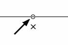
Positioning Marker
Move the pointer to position the bridge microjoint anywhere along the length of the pattern. If you want to choose a different pattern, click the right mouse button. Select the correct pattern and click the left mouse button. The positioning marker hesitates at the snap points so you can more easily select that point. When the position of the bridge microjoint appears correct, click the left mouse button.
![]()
To modify a microjoint after you have placed it, select Edit Microjoint and when you move into the work area, the pointer bounces between the existing microjoints on the part. Click the left mouse button when the pointer lands on a bridge or corner microjoint that you want to edit. You can then move into the Microjoint Window and specify new values.
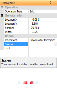
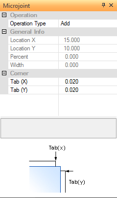
The Microjoint window appears any time that you begin to edit a bridge or corner microjoint. If you select a bridge microjoint, then the Bridge properties display in the lower half of the window. If you select a corner microjoint, then the Corner properties display in the lower half of the window. |
||
|
|
|
Bridge Microjoint Properties |
Corner Microjoint Properties |
|
|
|
|
Option |
Description |
|
Operation Type |
There are three options you can select from the drop-down menu: Add, Edit and Delete. |
|
Add |
Select Add from the Operation Type list to place additional bridge or corner microjoints. |
|
Edit |
Select Edit from the Operation Type list to edit any existing bridge or corner microjoints. |
|
Delete |
Select Delete from the Operation Type list to remove any existing bridge or corner microjoints. |
|
General Info |
The upper portion of the Microjoint properties window displays properties that are common to both bridge and corner microjoints. |
|
Location X |
This field displays the X coordinate for the bridge or corner microjoint. |
|
Location Y |
This field displays the Y coordinate for the bridge or corner microjoint. |
|
New Location Buttons |
Whenever you select the Location X or Location Y labels in the Microjoint window, a navigation button appears to the right of the display fields. You can clock this button, move into the work area, and modify the location of the microjoint. Use the pointer to position the microjoint and click the left mouse button when you are satisfied with the new position. |
|
Percent |
The paths on which you place microjoints are considered sets of individual segments (line and arc segments). The value that displays in the field represents a distance, expressed as a percentage, from the beginning of the current segment. (This is not the distance from the start point of the path.) You can type a number in this field to adjust the position of the microjoint. |
|
Width |
This field displays the width of the microjoint. You can type a new value to change the width. |
|
Bridge Microjoint Properties |
Appears if editing a bridge microjoint. The following properties are unique to bridge microjoints placed on the part perimeter. |
|
Placement |
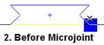
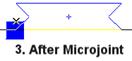
There are three options you can select from the drop-down menu: Before/After Microjoint, Before, After and None. These options are only available if you select the One Tool option from the Tool Num. list. The options control the tool placement in relation to the edge of the microjoint. Select Before/After to set the tool relationship to the left and right of the microjoint. Select Before to set the tool relationship to the right edge of the microjoint. Select After to set the tool relationship at the left edge of the microjoint. Select None if you don want the system to consider the tool placement in relation to the edge of the microjoint tool. As a rule, shearing tools are forced to the center of the bridge microjoint tool. |
|
Station |
The Station field displays the name of the tool you have selected for creating the microjoints. A navigation button appears to the right of the field after you select the label. The Turret window will appear after you click this button. You can then select a tool in the turret to create the microjoints. |
|
Tool |
The name of the designated bridge tool and its size appears in this field. |
|
Corner Microjoint Properties |
Appears if editing a corner microjoint. The following properties are unique to corner microjoints placed at the part corners. |
|
Tab (X) |
The X distance of the tab measured from the corner. |
|
Tab (Y) |
The Y distance of the tab measured form the corner. |
|
MJC |
The fields in this section display information about the Micro Joint Cutter property for the selected joint. |
|
Cut by machine |
This section is used to specify the use of an MJC (Micro Joint Cutter) device to process the joints. There are two options: Yes and No. If you select Yes, the joint will be cut by the MJC device. The system will determine the joint type and angle automatically. If you select no, the system will use the designated relief tool in the turret to process the joint, or adjust the tools along the paths using the parameters in the Punching Microjoints panel of the Material Information window to create the joints. |
|
|
|
|
![]()
To remove a punching microjoint, select Delete Microjoint and when you move into the work area, the pointer bounces between the existing microjoints on the part. When the pointer lands on a microjoint that you want erase, click the left mouse button.
![]()
To see punching microjoints, select View. If you want to see the punch microjoints during each redraw of the work area, make sure a check mark appears in the Show Features check box under Sequence Information in the Display Options panel of the Preferences window.
![]()
To remove bridge and corner microjoints, check ON the Bridge Microjoints option and click OK to delete only the bridge microjoints. Place a check mark in the Corner Microjoints check box and click OK to delete only the corner microjoints and click OK to delete.
![]()
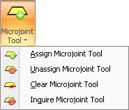
Note: The following options are only available when microjoints have been placed on the part. See Auto Microjoint and Place Microjoint as described above.
By clicking this command, the “Turret” or “Tool Inventory” dialog will open. The user must then select one tool as the microjoint tool to be used in this microjoint. Also, if this command is selected, the system will only snap to the Microjoint positions.
Note: A tool (or tools) must already be selected as the microjoint tool.
(See Machine>Turret Setup>Turret Window / List View for complete instructions.)
Operational Behavior
Click the Assign Microjoint Tool command, and then select a Microjoint tool from the Turret dialog by clicking on the tool and then releasing the mouse button.
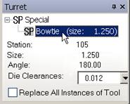
SP
Bowtie is a commonly
used tool for microjoints
Move the cursor into the workspace (the cursor becomes an X). A blue box will appear over every microjoint placement on the part when the X cursor is near. Left click to select the Microjoint placement.

The blue box indicates the presence
of a microjoint placement
Now begin the tool assignment by right-clicking to toggle through the microjoint assignments as illustrated here -
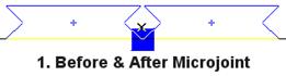
When the desired microjoint tool assignment appears on the part, move the cursor away and select another microjoint tool or keep the current microjoint tool and move to another microjoint, repeating the above steps.
When finished assigning microjoint tools, move the cursor into the Output pane at the bottom, right-click and select Clear to terminate the assignment action.
This command will clear all tool info in the Microjoint, and the “placement” in the Edit Microjoint dialog will be changed to “None.” Begin by clicking this command, left-click on the correct Microjoint, and the Microjoint tool will be removed from this Microjoint.
Clicking this command will remove (unassign) all the microjoint tools assigned to the part/sheet.
Notes:
1. If there is no microjoint placed on the part/sheet, the Assign/Unassign/Clear/Inquire Microjoint tool commands will be disabled.
2. The user will not be able to Assign/Unassign/Clear the microjoint tool on the part in sheet mode.
The Inquire option allows the user to verify the microjoint assignment for a part or sheet. Select Inquire from the Punch Microjoints Options menu and move into the work area. Click the microjoint that must be verified. The image of the tool appears, and its name, station, size and angles appear in the Tool window. You can inquire any or all the tools in the work area.