Turret Window
The
Turret window is a graphical representation of all the stations in your
machine. Scroll bars along the side and bottom allow you to navigate through
the window. A set of command buttons along the bottom also allows you
to manage your turret setup. The window is divided into these panels:
List View,
Illustration View,
Tool Inventory View
and M-Code View.

|
The
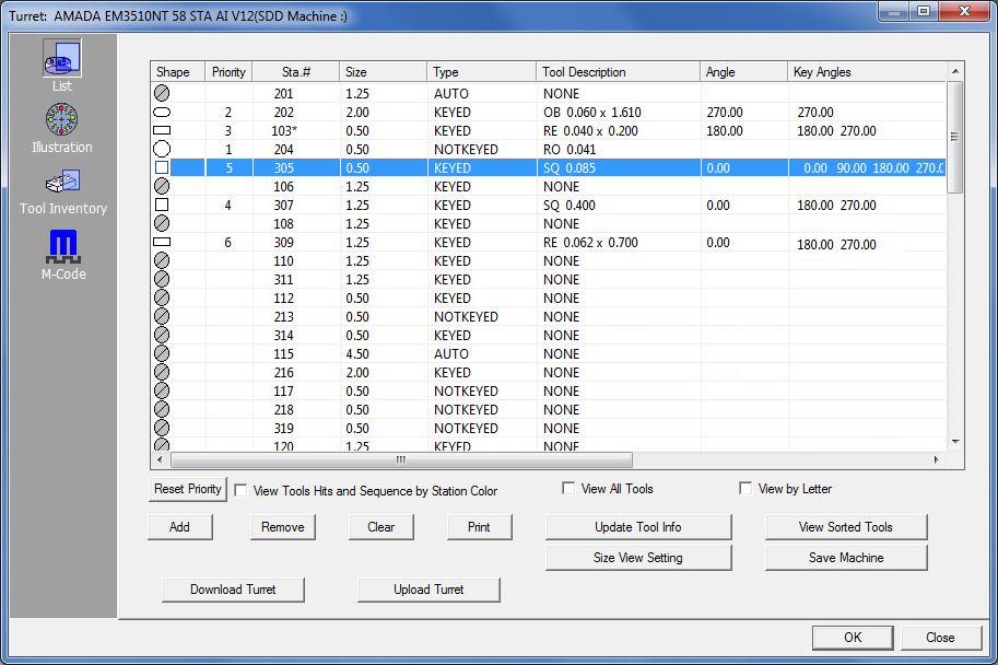
system will display the List view by default when you open
the Turret window. Columns are: Shape, Sta. # (Station Number),
Size, Type, Tool Description, Angle, Key Angles, Min Over Travel,
Max Over Travel, No Punch Zone and Tool Comment.
|
|
Column
Title |
Description |
Shape |
A
graphical icon that represents the tool shape appears in this
column. Double-click a station/row with a tool in it to open the
Station dialog to create and edit stations.. |
Priority
|
By
entering a value in the Priority option, the user can assign a
sequence priority to individual tools in the system in a standard
machine setup. (Compare this to the Sequence Priority feature
in Preferences>Tooling, which
can prioritize certain tool types
in a sequence, but not specific tools.) Double-click the tool/row
to open the Station window
and enter a value in the Priority field.
A
value of "1" assigned to a tool will cause that tool
to be sequenced first. The user may prioritize the tools as desired.
See Creating &
Editing Stations for more info on assigning priorities to
tools. Click the Reset Priority
button to return all priority values to the default setting, which
is pulled from the Sequence Priority feature in Preferences>Tooling.
When
the user hits the Save Machine
button in this window the tool sequence priorities are then saved
with the machine and become the default
for this machine. (This will NOT affect the original Sequence
Priorities in Preferences>Tooling.)
When
a sheet using this machine is sequenced, these priority values
will be passed on to the Tool
Sequence Priority Window in Sequence Features. Tool priorities
can then be adjusted in that window on a per-session basis. |
Sta.
# |
The
station or tool ID number.
A
letter displaying next to the Station number indicates that the
tool has been designate for special use. These letters include:
T (Trimming), R
(Remnant), L (Reliefs),
P (Pierce), S
(Scribing), M (Microjoints).
An
asterisk (*) indicates that the tool has already been assigned
and is in use.
(See
Station Tool Information Dialog.) |
Size |
The
size of the station. This column displays the actual size, in
inches, or the letter size equivalent. |
Type |
The
station type -
KEYED The station is keyed to
hold the tool in a given angle; NOTKEYED
The station has no key and is used with ROUND tools; MANUAL
Allows the user to override the original key position; AUTOINDEX Tool can freely rotate
to any angle as needed;
CLAMP Used for staging a clamp
with the tool holder (for Trumpf-style clamp holders). |
Tool
Description |
A
description of the tool currently installed in the station. If
a station is empty, then “NONE” appears in the field. |
Angle |
The
angle of the tool when it is assigned to a turret station. |
Key Angles |
Additional
angles that the turret station can allow if needed. |
Min.
Overtravel |
The
minimum amount of allowed overtravel. |
Max.
Overtravel |
The
maximum amount of allowed overtravel. |
No Punch
Zone |
The
area around the clamps that cannot be punched. |
Tool
Comment |
Enter
information about the tool, for example the location where the
tool itself is stored. When saved, this read-only information
is viewable in the Tool
Comment column in the Tool Inventory - List
View and Tool Inventory
panels.
Note: When
generating NC code, data from the Tool Comment column will be
added to the setup sheet and will be viewable in the NC Sequence
Viewer.
For
info on entering a comment see the Tool
Information Dialog. |
Option |
Description |
View
Tool Hits and Sequence by Station Color |

This is a toggle switch. If you activate the option, the tool hits
appear on the part or sheet in the colors you assigned using the
Station Color List or Station Color Button in the Station window.
|
View
All Tools |
This
is a toggle. If you activate the option, the system only lists
those tools in the Tool List that are available when the selected
turret station is of the same size and type. |
View
by Letter |
This
is a toggle. If you place a check mark in the check box, the system
will display the station sizes as letters in the Turret and Station
windows. If you remove the check mark, then the actual stations
sizes display. |
Command Buttons |
Reset
Priority |
Click
to return the Priority values in each cell to the default setting.
See Priority above for full info. |
Add |
To place
tools in the turret click the Add button and the Turret
window displays the Tool List on the right side. Tool List will
display the tools in the currently loaded Tool Inventory. The
tools are grouped by type, i.e., Round, Double D, Single D, Obrounds,
Squares, etc.
You
can save tools with the machine setup to create a standard turret
load.
Notes:
1) When you use the Auto Sheet, Auto Part or Assign options for
tool assignments, the system automatically adds the tools to the
turret.
2) You can only place tools in empty turret stations, i.e. stations
having the Tool Description of “None”.
3) When you select a tool in the Tool List that matches a station
size in the turret, the system will highlight the corresponding
station(s) in List View to indicate those stations that will accept
the selected tool.
4) The system remains in Add Tool mode until you select another
option.
5) The special tools appear at the very end of the Tool List. Note:
Changes made to a Special Tool in the Special
Tool Designer module will automatically be passed to the Tool
Inventory. |
Remove |
To
remove a tool from a station, select the station containing the
tool and then click the Remove button in the turret window. |
Clear |
Click
the Clear button if you want to completely change your turret
setup, or remove all of the unused tools from the turret. A message
window appears asking if you want to clear All Tools, or
just the Unused Tools from the turret. Select the appropriate
option and click OK. Click Cancel to exit without clearing any
tools from the turret. Remember that Clear Tools will not remove
tools from Fixed Stations.
|
Print
Turret |
Click
the Print button if you want to print your turret setup. When
the system prompts you for confirmation, press <Y> for Yes
or <N> for No. The report lists the station number, size,
type, tool, angle, over travels, key angles and no punch zones.
The report may be split over several pages, but the station numbers
appear on all the pages. |
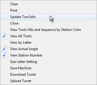
Update
Tool Info |
If
you have loaded a machine or sheet that does not include tool
information and the Tool Inventory does include tool information,
use the Update Tool Information button to update every tool in
the turret. (See also Update Button under Station
Tool Information Window.) |
View
Sorted Tools |
The
View Sorted Tools button is a toggle. You can use this button
to display only those tools, sorted by shape and size, which are
actually used to process the part or sheet. The remaining stations
without tools are hidden from view. Click the button again to
view all the turret stations and installed tools. |
Size
View Setting |
Some
machines use a letter designation, such as A, B C, etc., to indicate
the station size and type, while other machines use the actual
tool size to define the turret station size. The Size View button
allows you to define the station size and use either a letter
designation for the station or the actual size.
Click
on the Size View Setting button and the Letter Tool
Size dialog appears.
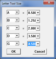
Clicking
on any drop-down list on the left displays the letter designation
for a particular station size in the turret. Clicking on any drop-down
list on the right displays the actual station sizes.
If
necessary, you can correct the letter designation and size for
each station type. Select a letter designation from one of the
lists on the left and then select the appropriate size from one
of the lists on the right. Click OK to save the changes
or click Cancel to exit without saving. |
Save
Machine |
Click
the Save Machine button to save any changes. If the system prompts
you to overwrite the existing machine, click OK.
Saving Changes to the Turret
The changes you make in the
turret are saved when you save the sheet. However, if you also
want to save this as a new machine file, use the Save As… option
under the File menu to assign a new name. (See Machine
File.)
Note: Changes made to a Special Tool
in the Special Tool Designer
module will automatically be passed to the Tool Inventory. |
Download
/ Upload Turret |
Download
an SDDJ Turret Layout to the AP100US Turret File and tool inventory.
(Available only if connected to an SDDJ Server.)
Upload
an AP100US Turret file to the SDDJ database.
Note:
These options are available only for AP100US users, who are connected
to an SDDJ Server. |
OK /
Close |
Click
OK to save any changes
and exit The Tool Inventory window.
Click
the Close button to exit the Tool Inventory window without
saving any changes. |
Notes: |
|
1. You
can toggle between the List, Illustration and Tool Inventory views
by clicking their respective icon buttons along the left-hand
side of the Turret window. |
2. If
your turret does not display any stations or just one station,
select the Turret Info option from the Machine menu and
define the station information before attempting to add tools
to the turret. |
3. If
you are using an existing machine, make sure the information for
each station is correct. If you are creating a new turret, you
will need to enter the information for each line. (See Creating
and Editing Stations .) |

Clicking the
Illustration button will display a graphical layout of the currently
loaded turret within the Turret Illustration window. The station number
for all stations displays by default.
While
the cursor is over the display, depress and hold the center mouse wheel
and drag the entire display so that a particular station is at the center.
Roll the mouse wheel button to zoom in and zoom out.
(See
Turret
Illustration and Design and Turret
Types for more information.)
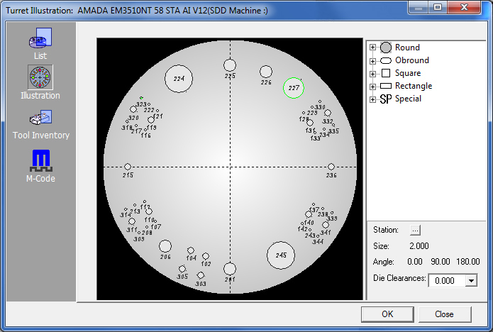
Passing
the cursor over a turret station will highlight the station in blue and
its number in red. The system will also display information for that station
in a tag. If a station has a tool assigned, the tool will be highlighted
in green, and tool information will display in the tag. See the illustrations
below.
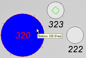
If there is no tool currently installed in the
station the word “Free” will appear
in the tag after the station number.
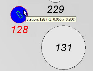
When
a tool is installed the tag indicates the tool type and tool size (RE
- rectangle
-, size = 0.035 x 0.400). The tool installed in Station 128 is outlined in green.
Double left-click
on any station to open the Station dialog.
From here edit station characteristics. (See
Creating and Editing Stations for more info.)
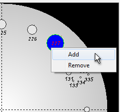
Loading tools
into the turret is permitted in this window. Right-click on a station
in the turret illustration and click on Add to open the Add panel.
From the panel drag and drop tools from the Tool Inventory into the stations
in the Illustration view. To
remove a tool from a station, right-click on the station and click Remove.
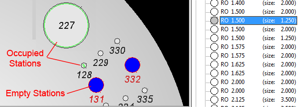
When a tool
is selected (as in the diagram above) all empty stations suitable for
the tool (according to size) will be highlighted in blue. Occupied stations
display in green. Drag and drop a tool from the Tool Inventory on the
right over to a BLUE station
in the turret illustration on the left.
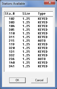
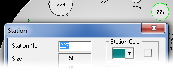
Click on
the Station
button to open the Stations Available dialog box shown on
the left. After a tool is selected in the Tool Inventory panel the button
becomes available. Select an available
station and click OK to place the tool that is already selected into the
station.
Right-click
a blank area of the turret illustration to display the flyout menu with
turret setup options as discussed above in Turret Window – List View .

|
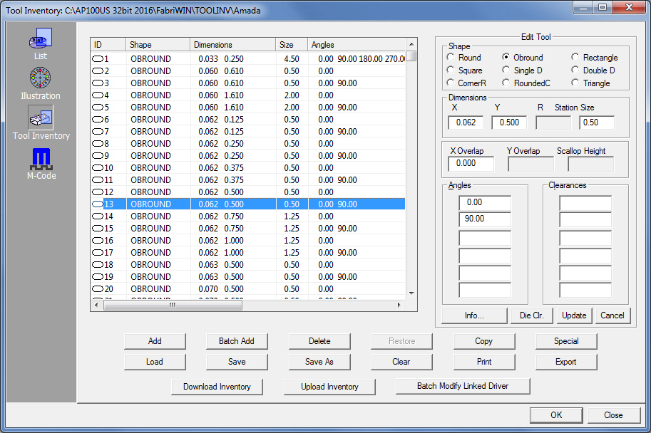
If
you click the Tool Inventory tab, the system will switch
to Tool Inventory mode and list all the tools in the currently
loaded Tool Inventory.
To
edit an existing tool, double-click any Tool/Row to open the Edit
Tool panel shown here. The panel will be populated with values
for the current tool that may be edited. |
|
Column
Title |
Description |
ID |
Displays the Tool ID. |
Shape |
The
shape of the tool (such as “Round” or “Rectangle”) is given here. |
Dimensions |
The
Dimensions of the tool is shown here. |
Size |
The
Size of the tool is shown here. |
Angles |
Displays
the angle value that was entered in the Add New Tool dialog. |
Clearances |
Displays
the Die Clearance value(s) that have been entered for the Tool.
|
Tool
Comment |
Enter any necessary information about the
tool, such as where the tool itself is stored.
Tool Comments must be added through the Tool
Information Dialog.
Note:
When generating NC code, data from the Tool Comment column will
be added to the setup sheet and will be viewable in the NC Sequence
Viewer. |
Option |
Description |
Add |
The
Add option allows the user to add a tool to a new or existing
inventory. Click the Add button and the Add New Tool
dialog displays on the right side of this window. For info on
adding new tools, see Creating and Editing
Tools.
To
display the Edit Tool dialog in this place, double-click
any existing tool in the inventory. |
Batch
Add |
Batch
Add can add multiple tools to the inventory at one time, instead
of adding individual tools one by one.
Click
the Batch Add button and the Tool Setup windows displays. Begin
by picking a tool inventory from a listed company, and then simply
check the tools you want to add and click Finish button. The tools
you selected are now added.
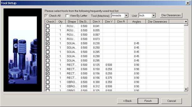
Tool
Setup Window
Refer
to these instructions for Batch Adding.
In
the first dialog box, select a tool inventory from a specific
manufacturer.
Click Next
to go to the main Tool Setup dialog. |
|
In
the next Tool Setup dialog, check the tools that are to
be Batch Added and click Finish to load those tools.
Click Back to return to the dialog above if necessary. |
|
|
Delete |
The
Delete option removes the currently selected tool from
the Tool Inventory. Click the line belonging to the tool you want
to delete, and then click the Delete button. The tool is
removed from the list. If you accidentally delete the wrong tool,
click the Restore button to restore
it. |
Restore |
The Restore
option reverses the Delete command and
restores a tool. Click the Restore button and the last
tool you deleted reappears in the Tool Inventory.
Note:
You must use Restore before exiting the Tool Inventory window.
Once you save your changes and exit, you cannot restore any deleted
items. |
Copy |
To add
a tool that is similar or identical to an existing tool in your
inventory, click the Copy button. Click the line belonging
to the tool you want to copy and then click the Copy button.
The
Copy Tool panel (which functions in the same way as the Add New Tool
and Edit
Tool dialogs) will appear and display information
for the original tool. Modify the information as needed. When
the information is correct, click OK and a copy of the
tool appears in the list. |
Special |
Special
tools are tools having custom shapes, rather than standard shapes.
You must draw and record the station information for your special
tools before you can add them to your Tool Inventory. (See Designing Special Tools.)
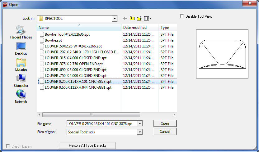
To
add an existing special tool to the inventory, click the Special
button. When the Open dialog box appears, navigate to the desired
drive and folder, and then select the file name of the special
tool. Click Open to load the special tool into the current
inventory. You can load as many special tools as needed. Click
Close to exit the Open dialog box.
|
Notes:
Special tools cannot be edited in the Tool Inventory module. To
edit a special tool, select the Design Special Tool…
option from the Tool menu to open the Special Tool window.
When a Special Tool is edited in the Special Tools Designer, changes
made will automatically be updated to the Tool Inventory.
See
Designing Special Tools.
|
Load |
The
Load button displays the Open dialog box. If you want to
change an existing tool inventory, use Open to load that tool
inventory so you can make corrections.
In
addition to standard inv files, the user may choose to load from
Tool Inventory files in .XLS or .CSV formats. From here it is
also possible to create and edit .xls and .csv files. See Export below for more info on
this. |
Save |
You
must save the Tool Inventory after modifying it. If you have created
a new tool inventory, click the Save As button.
Navigate to the desired drive and folder, and then type a name
in the File name: text box. Click Save and then Close
after the system saves your tool inventory.
For
an existing tool inventory that you want to save under the same
name, click the Save button.
Note:
The system prompts you save the changes before you exit. Press
<Y> for Yes, <N> for No, or <Escape> to cancel.
If you press <N>, any changes you made are permanently lost.
If you want to save the inventory under a different name, press
<Escape>, and then use Save As. |
Save
As |
You
must save the Tool Inventory after modifying it. If you have created
a new tool inventory, click the Save As button. |
Clear |
The
Clear button allows you to clear the current inventory
and start a new inventory. You may want to do this if you are
creating several tool inventories. However, if you use Clear,
make sure to save the tool inventory under a different name before
you exit the Tool Inventory. Otherwise, you will overwrite the
contents of the original tool inventory. |
Print |
If you
want to print a list of the Tool Inventory, click the Print
button. The Print Options window appears. Select either Current
Screen or Entire Inventory, and then click
OK.
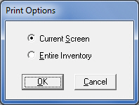
Select
Current Option if you
only want to print those tools that are currently visible within
the Tool Inventory window.
Select
Entire Inventory if you
want to print every record in the Tool Inventory. |
Export |
To
export Tool Inventory files in .XLS or .CSV formats, click Export. The Save As dialog will
open allowing the user to save directly to the TOOLINV folder
in the AP100US installed folder in either .xls or .csv format.
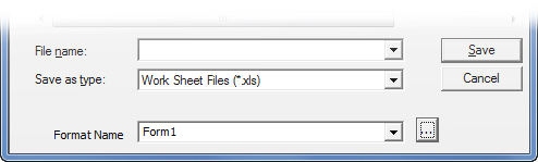
The
Save As folder contains a Format
Name and button. The user may select from existing formats,
or click the button to open the Format Options window to create
or edit formats.
See
Exporting Files in XLS or CSV formats
in the Material Files folder for more info on creating and editing
.xls and .csv files. |
Download
/ Upload Inventory |
Download
an SDDJ Tool Inventory to the AP100US Tool Inventory File. Upload
a Tool Inventory to update the SDD Tool Inventory. (Available
only if connected to an SDDJ Server.) |
Batch
Modify Linked Driver |
If a user
needs to map a Standard Item to an item that needs a value input,
this button may be selected to open the Punch
Condition Mapping window. Here the
user will see current M-Codes and make changes to the M-Codes
mapping as needed. |
OK /
Close |
Click
the OK button when you have recorded all the additional tool information.
Click Cancel to exit the Tool Information window without saving
any changes. |
Turret Window - M-Code View
 AP100US
supports MCA files that contain conditions for Special Tools. Used with
Combo and Punch machines, this read-only MCA info can help the user to
maximize special tool actions, which will speed up special tool processing
and result in an improved Run Time. See View
Run Time for more info.
AP100US
supports MCA files that contain conditions for Special Tools. Used with
Combo and Punch machines, this read-only MCA info can help the user to
maximize special tool actions, which will speed up special tool processing
and result in an improved Run Time. See View
Run Time for more info.
When a newer
model Amada punch or combo machine is loaded, along with an MCA file (see
Machine>Description window for
more info) the MCode icon displays. Click the button to display the M-Code
panel.
.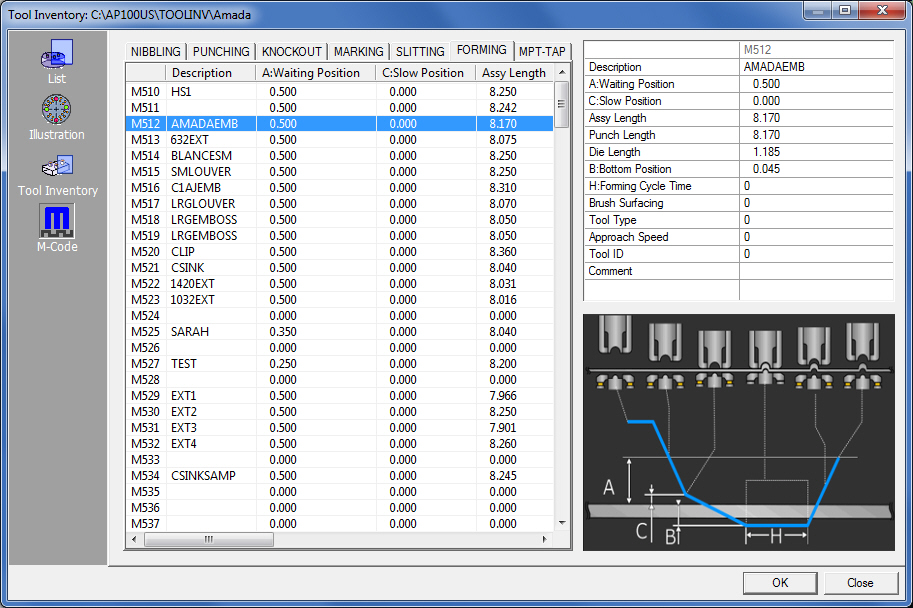
When a tab is selected (such as Forming shown
here) the image
at lower right shows an explanation of columns in that tab
Importing MCA Files
MCA files that are created by an operator on the machine controller can
be imported into AP100US. Using a portable memory device attached to the
machine controller, export a copy of the MCA file and then place that
copy in the C:\AP100US\ConditionFile folder. The imported MCA file can
then be opened in AP100US by clicking the Add
button next to the Machine Settings>MCA File field. When the Open dialog appears, double-click
a .mca file to add it to the field. See the Machine>Description window for
more info.
Tabs and Column Headers
NIBBLING
(Punching out a part or slug using many tool hits in rapid succession.)
Description: The description or
name assigned to the tool by the operator/user when the tool was first
added to the inventory.
A: Waiting Position: Position of
a tool above the sheet when the sheet is in motion.
B: Bottom Position: Maximum depth
of the tool after the hit when it has passed through the sheet towards
the die.
Comment: Comment added to the tool
by the operator/user.
PUNCHING
(Use of punching tools to process a sheet as opposed to laser cutting.)
Description: The description or
name assigned to the tool by the operator/user when the tool was first
added to the inventory.
A: Waiting Position: Position of
a tool above the sheet when the sheet is in motion.
C: Slow Position: Position of the
tool when it slows down just prior to the actual hit.
B: Bottom Position: Maximum depth
of the tool after the hit when it has passed through the sheet towards
the die.
Comment: Comment added to the tool
by the operator/user.
KNOCKOUT
(Removing a slug with a single hit from a tool.)
Description: The description or
name assigned to the tool by the operator/user when the tool was first
added to the inventory.
A: Waiting Position: Position of
a tool above the sheet when the sheet is in motion.
C: Slow Position: Position of the
tool when it slows down just prior to the actual hit.
Assembly Length: Overall length
of actual tool.
Punch Length: Length of the actual
punch that is inside the tool.
Die Length: Length or overall thickness
of the die itself.
B: Bottom Position: Maximum depth
of the tool after the hit when it has passed through the sheet towards
the die.
High Speed Knockout: Actual speed
of the tool when making the hit. The user may choose Normal or High.
Tool ID: The ID number assigned
to the tool.
Comment: Comment added to the tool
by the operator/user.
MARKING
(Use of a special tool to stamp a name or logo on a part.)
Description: The description or
name assigned to the tool by the operator/user when the tool was first
added to the inventory.
A: Waiting Position: Position of
a tool above the sheet when the sheet is in motion.
C: Slow Position: Position of the
tool when it slows down just prior to the actual hit.
Assembly Length: Overall length
of actual tool.
Punch Length: Length of the actual
punch that is inside the tool.
Die Length: Length or overall thickness
of the die itself.
B: Bottom Position: Maximum depth
of the tool after the hit when it has passed through the sheet towards
the die.
High Speed Marking: Select Normal
or High to control the speed of a marking hit.
Tool ID: The ID number assigned
to the tool.
Comment: Comment added to the tool
by the operator/user.
SLITTING
(Similar to shearing, a tool and die work together to create a
"scissor" effect to make a slit in the material.)
Description: The description or
name assigned to the tool by the operator/user when the tool was first
added to the inventory.
A: Waiting Position: Position of
a tool above the sheet when the sheet is in motion.
Assembly Length: Overall length
of actual tool.
Punch Length: Length of the actual
punch that is inside the tool.
Die Length: Length or overall thickness
of the die itself.
B: Bottom Position: Maximum depth
of the tool after the hit when it has passed through the sheet towards
the die.
Bottom Position End: The final
position of a tool when the hit is completed.
Tool ID: The ID number assigned
to the tool.
Comment: Comment added to the tool
by the operator/user.
FORMING (The use of a tool to
modify the geometry of a part rather than removing a portion of the material.)
Description: The description or
name assigned to the tool by the operator/user when the tool was first
added to the inventory.
A: Waiting Position: Position of
a tool above the sheet when the sheet is in motion.
C: Slow Position: Position of the
tool when it slows down just prior to the actual hit.
Assembly Length: Overall length
of actual tool.
Punch Length: Length of the actual
punch that is inside the tool.
Die Length: Length or overall thickness
of the die itself.
B: Bottom Position: Maximum depth
of the tool after the hit when it has passed through the sheet towards
the die.
Forming Cycle Time: The time required
to complete one complete forming hit.
Brush Surfacing: This switch (1=on,
0=off) enables the Floating Brush Table, which raises or lowers a brush
table under or near the turret. The machine in use must be equipped with
an FBT.
Tool Type: Select from Normal,
Ram Hold Down (With the tool at the final bottom position it will briefly
hold in place to complete the deformation of the material.) or High-Speed
forming.
Approach Speed: Speed of the tool
as it nears the material to execute a hit.
Tool ID: The ID number assigned
to the tool.
Comment: Comment added to the tool
by the operator/user.
MPT-TAP (Multi-Purpose Tool for
Tapping or drilling out a threaded hole.)
Description: The description or
name assigned to the tool by the operator/user when the tool was first
added to the inventory.
A: Waiting Position: Position of
a tool above the sheet when the sheet is in motion.
B: Bottom Position: Maximum depth
of the tool after the hit when it has passed through the sheet towards
the die.
Comment: Comment added to the tool
by the operator/user.