Option
Description
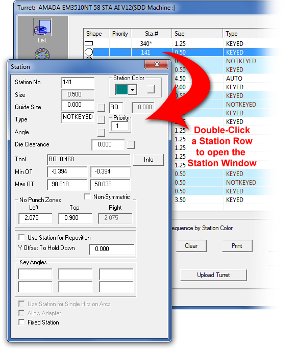
Station No.
The station number as assigned by the turret or station layout.
Station Color List
To change the color for a specific station, click the arrow button and select a standard color from the drop-down pallet. Click the Color button to open the default Color window.
Size
The size of the station. If letters designate your station sizes, return to the Turret window and use the Size View button to toggle between station sizes and letters. See Size View.
Guide Size (in)
The size of the tool assembly within the station. You also have the option of specifying a custom guide display for special relieved tools. The software will display the guide area relative to the angle being used for the tool. To view the guide display in Part or Sheet view, enable Show Guide Size in the Display Options panel of the Preferences window.
![]()
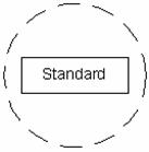
If you type a value greater than zero in the Guide Size (in) text box, the toggle button and field to the right become active. The software displays the standard R (Round) guide, indicated by a dashed round hole:
![]()
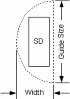
To specify an SD, or Single D guide (or one relieved side), click the toggle button until SD appears in the guide type field. The text box to the right of the guide type field becomes active. Type the Width for the guide in the text box. The software displays the Single D guide type in Part or Sheet view using the specified value:
![]()
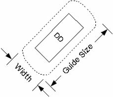
To specify a DD, or Double D guide (or two relieved sides), click the toggle button until DD appears in the guide type field. The text box to the right of the guide type field becomes available. Type the Width for the guide in the text box. The software displays the Double D guide type in Part or Sheet view using the specified value:
Notes:
When using the SD or DD guide types, the guide sizes display relative to the moving angle of the sequenced tool. For example, if the sequence rotated the SD guide size by 180 degrees, the large radius side would display facing downward if the tool was in an auto-index station.
The guide size shape always displays parallel with the angle of the tool.
Type
Click the button to the right of the text box to toggle through the station types: KEYED, NOT KEYED, AUTO (auto-index), MANUAL and CLAMP.
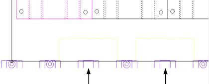
The punch holder support feature specifically uses the CLAMP station type to display those tools that are used with the clamp positions. The illustration below depicts those stations in the turret that have been designated as CLAMP-type stations. The tools have been removed from the clamp positions as indicated by the arrows.
Notes:
When you designate a station as a CLAMP, the software will prompt you to remove the tool currently loaded in the station.
The software compares the number of CLAMP stations in the turret with the number of clamps specified in the machine setup. If the number of CLAMP stations in the turret exceeds the number of stations specified in the machine setup, the system prompts you to reset the number of clamps: “Maximum clamps have been used. Do you want to reset the Num Clamps in Machine Info?” Press <Y> to reset the Num Clamps value, or <N> to cancel.
The software will allow you to drag a clamp position into a non-tool region, but if a tool is used, the system cannot load the clamp in that position. Once you move the clamp, the software will maintain the clamp station during the current session and for the sheet. The clamp positions are saved with the sheet information in the same manner as if they were tools.
Angle
Click the button to the right of the Angle text box to toggle between the available angles for any tool currently in the station. For an auto-index station, you can type the starting angle, provided it is not zero. The possible angles are determined by the values in the Key Angles fields and the keyed angles specified for the tool in the Tool Inventory. These are combined to determine the possible angles. For example, if the station has 0, 90 and 180 as its keyed angles, the possible angles are 0, 90, 180 and 270. However, if the station has a keyed angle of 90 and the tool 0 and 90, the possible angles are 90 and 180.
![]()
Priority
By entering a value in the Priority option, the user can assign a sequence priority to individual tools in the system in a standard machine setup. See Turret Window - List View>Priority for info.
Die Clearance
This field displays the die clearance, if one has been set. Click for more info on die clearances.
Tool
This field displays the tool installed in the station.
![]()
To customize the function of a tool, click the Info button to open the Station Tool Information window. See Station Tool Information Window.
Min OT
These text boxes contain the X and Y minimum overtravels for the selected station. Type the X minimum overtravel in the first text box and the Y minimum overtravel in the second text box. When you view the sheet, the values indicate the furthest distance in the –X and –Y directions that the machine (or head) can travel. The numbers reference from the lower left corner of the sheet. Some machines can travel in these directions (the settings display as negative numbers), while other machines cannot (the settings display zero).
Max OT
These text boxes contain the X and Y maximum overtravels. Type the X maximum overtravel in the first text box and the Y maximum overtravel in the second text box. When you are viewing the sheet, these values indicate the furthest distance in the X and Y directions that the machine (or head) can travel away from its starting point.
WARNING!
Overtravels are EXTREMELY IMPORTANT for generating accurate programs. You will find this information in the programming manual for your machine.
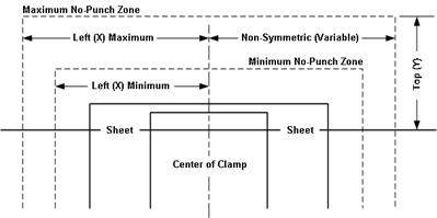
The No Punch Zone allows you to specify a safety or clamp dead zone around the clamps. Type the X distance in the Left text box and the Y distance in the Top text box.
Notes:
1. The X or Left value is the horizontal distance from the center of the clamp to the edge of the dead zone. The Y or Top value is the vertical distance from the sheet to the top of the dead zone.
2. The software displays a “Hits out of range” error if you attempt to sequence a pattern that falls within a clamp dead zone. If you encounter this error and do not correct it (such as moving the clamp or repositioning the sheet), the pattern is omitted when the software generates the program code.
3. The outer dashed line represents the Maximum No Punch Zone and the inner dashed line the Minimum No Punch Zone. The display of the outer and inner zones reflect the maximum and minimum No Punch Zone values defined in the turret. The display of the dead zones is dynamic; the zones update and change size when a tool having different No Punch Zone values for its station is used.
Non-Symmetric
If you enable this option, you can define different no-punch zones on the left and right side of each clamp.
No Punch Zones – Non-Symmetric Fields
Left
Type the no-punch zone for the left size of the clamps in this text box. If Non-symmetric is disabled, the setting is also used for the right side of the clamps.
Top
Type a no-punch zone for the top of the clamps in this text box.
Right
If Non-Symmetric is enabled, type the no-punch zone for the right side of the clamps in this text box.
Use Station for Reposition
Some machines can only reposition at a certain station, while other machines have several stations where repositions can occur. If you enable this option for a station, the software ensures that the station is in the punching location before the reposition. If the last punch before a reposition is a station not designated for repositioning, the software will move to the closest designated station and use it for the reposition. If you enable this option, you must also specify a value in the Y Offset To Hold Down text box.
Y Offset To Hold Down
This is the distance from the station center point to the hold down post in the Y direction. Forward (i.e., in front of the turret) of the station centerline would be a negative number, behind (i.e., toward the turret) would be a positive number. The value of zero indicates that the hold down is in line with the punching or cutting head.
Key Angles
You can define up to six angles for a keyed station. When a tool is loaded into a keyed station, the keyed angles for that station are combined with the angles allowed for the tool. For example, if the station has the keyed angles of 0, 30 and 45, and the tool has the allowed angles of 0 and 90, the combined angles would be 0, 30, 45, 90, 120 and 135.
Use Station for Single Hits on Arcs
Select this option if you want the tool in this station to be used exclusively for creating arcs with a single hit of the tool.
Allow Adapter
If you enable this option, the system will disable the tool filtering and place tools in this station either manually or automatically. The system will place a tool in the station provided that the tool size is smaller than the station size.
Fixed Station
If you enable this option, the station becomes fixed. The software will not remove a tool from a fixed station in the turret. If you want the software to replace the tool in the station when needed, remove the check mark.
Notes:
If all the punches use only 0- and 90-degree keying, you do not need to define the angles, but you must specify which stations are keyed. If you define keyed angles, you must also specify 0 and 90 if so allowed for the station.
PDC Station
ATC Station
This option is driver dependent, and only appears if a PDC or ATC compatible machine is in use.