(Specifying
Tool Shapes and Parameters)
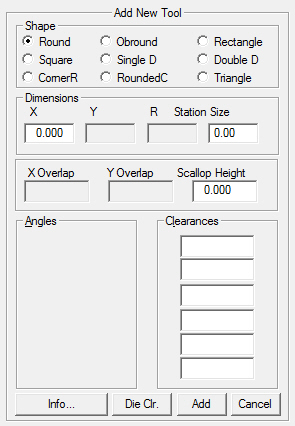
Specify the actual shape
or name of the new tool. Select one of the following names in
the Shape section of the Add New Tool window and then type
the values in the appropriate Dimension and Station Size text
boxes. The following table outlines the required parameters for
each tool shape.
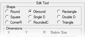
Note: When the Edit Tool dialog is
open, it is not possible to choose a new shape for an existing
tool. However, any other values may be configured for an existing
tool. If the Edit Tool dialog is open, begin Editing at Dimensions and Station
Size. |
Shape |
Parameters |
Round
(RO) |
A
round punch. You must specify an X dimension and Station
Size. |
Square
(SQ) |
A
square punch. You must specify an X dimension, Station
Size, and any angles allowed for the tool. |
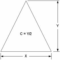
CornerR
(CR) |
A
four-way corner radius. The Y dimension is the overall
width of the tool, while the X dimension is the radius
and the extension of the web beyond the radius. The radius refers
to the actual radius of the four radii. See the Corner Radius
Tool diagram below. |
|
|
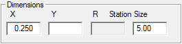
Obround
(OB) |
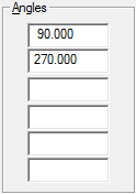
An
Obround punch. Specify an X dimension, a Y dimension,
and any angles allowed for the tool. |
Single
D (SD) |
A
Single D punch. Specify an X dimension, a Y dimension,
and any angles allowed for the tool. |
RoundedC
(RC) |
A
rounded-corner rectangle. This describes a rectangle punch that
consists of radius corners. Specify an X, Y, and
R dimension (the radius of each corner), and any keyed
angles. |
Rectangle
(RE) |
A
rectangular-shaped punch. Specify an X dimension, Y
dimension, Station Size and any angles allowed for the
tool. |
Double
D (DD) |
A
Double D punch. Specify an X dimension, a Y dimension,
and any angles allowed for the tool. |
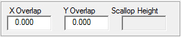
Triangle
(TR) |
A
triangle-shaped punching tool. The X dimension is the overall
width, the Y dimension the overall height, and the C
value is the distance from the base of the triangle to the center
point of the tool. The C value replaces the R when
Triangle is selected as the shape. The system automatically divides
Y by one-half to calculate C. For example, if you
specify Y = 1.5, the system returns the value of 0.750
for C by default. If necessary, you can overwrite this
value. |
|
|
|
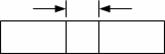
Overlap
describes the amount the tool hits should overlap in the horizontal
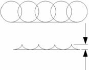
and vertical directions when punching patterns. Scallop height
is the amount of scallop created when the system nibbles patterns
with round tools. |
|
|
|
Tool
Overlap X |
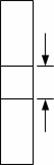
Tool
Overlap Y |
Scallop
Height |
|
Option |
Description |
X Overlap |
For
non-round tools, the X Overlap value allows you to specify the
distance the tool should overlap in the X or horizontal direction. |
Y Overlap |
For
non-round tools, the Y Overlap value allows you to specify the
distance the tool should overlap in the Y or vertical direction. |
Scallop
Height |
For
round tools, Scallop Height allows you to define the height of
the scallop formed during a nibble process. The smaller the value,
the less the scallop. |
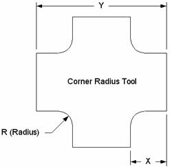
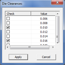
Die
Clearance is the space between the cutting edge of the punch and the cutting
edge of the die. The size of this space is defined by the thickness and
type of material being punched. For example, a 16-gauge blank may require
a value of 0.011.
Die
Clearance must be optimized for best performance. A clearance that is
too wide or too tight may spoil edge quality and even ruin the tool.

|
Info… |
The
Info… button displays the The Tool Information dialog.
Record supplementary preferences for the selected tool (such as
Travel Direction and Tool Comments) by enabling the Add
Additional Information to the Tool
option in the Tool Information window.
|
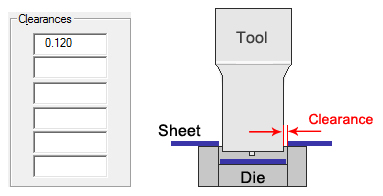
Die Clearances |
Click
to open the Die Clearances dialog. |
|
|
If
clearances are not manually entered, click Die
Clr. to open a dialog with common die clearance values.
Check one or more values to assign them to the tool.
Click
Apply to load these values into the Clearances fields
shown above. |
Add
Update |
After
a completely new tool has been created, click the Add
button to add it to the inventory. If you are editing an existing
tool, that same button will read "Update."
Click it to update the tool.
Note:
When exiting the main Tool Inventory window, it's still necessary
to hit Save. |
Cancel |
Click
Cancel to close the Add New Tool or Edit Tool dialog,
without saving any changes. |