Designing
& Defining Special Tools & Cluster Arrays
A
special tool is any tool configured of a non-standard shape. A non-standard
shape indicates the tool is something other than a round, obround, rectangle,
square, single D, double-D, four-way radius, triangle, or rounded corner
rectangle.
Options
on the Tool Assign tab > Special Tool submenu allow you to create
and manage special tools quickly and easily. Once you create a special
or cluster tool and add it to a tool inventory, you can use the Place
Tool Hits option on the Group Pattern submenu (Draw
menu) to position the custom pattern on your part.
You
can use the Define Special Tool and Define Cluster Tool Array options
on the Special Tool submenu to create special tools and then assign those
special tools to identical cluster patterns.
Options covered on this page are -
|
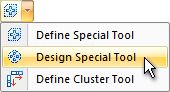
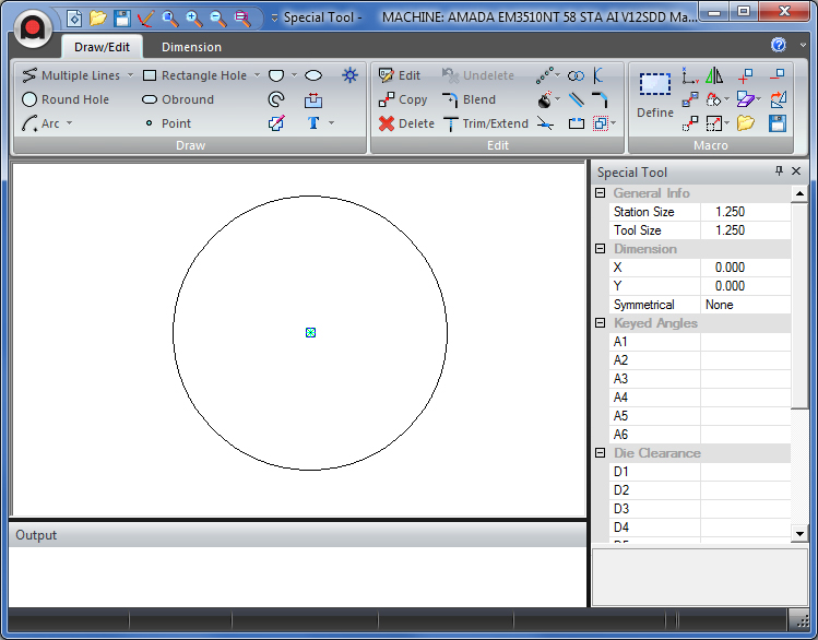
To draw a special tool, select
Design Special Tool from the Special Tool
submenu to open the Special Tool Designer window. The window displays
a circle having a reference point at its center, and the Special
Tool Information window. The circle represents the actual tool
size. If you modify the Tool Size value, the circle resizes accordingly
only after you place patterns within it. The Tool Size parameter
is saved with the special tool.
Note:
The system automatically begins a new special tool each time you
start the Special Tool application.
Note: When defining a Special
Tool and assigning tools, AP100US can snap not only to the default
point, but also to an additional point placed by the user.
Note: Changes saved to a
Special Tool in the Special Tool Designer module will automatically
be passed to the Tool Inventory.
The Draw/Edit/Macros
and Dimension
menus function as they do in AP100US.
|
|

|
If
the Special Tool properties window is not open, click the Amada
"A" to open the main Special Tool menu.
Click
on Special Tool info as shown in the image.
|
|
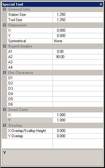
Use
the Special Tool properties window to define the tool. The window
disappears if you select another option. Open the window by selecting
Special Tool Info in the menu bar. You can
draw the tool after you have typed all the values.
When
defining a special tool, the system should use the overall X and
Y values of the Define box and transfer them to the X and Y values
in the Dimension fields. This will at least give the user the
overall size of the tool.
Notes
on snapping to points:
The point
or pattern in the Shape Definition can be used as the Center of
the Tool.
Actual
coordinates can be entered in the Coordinates
panel when placing a snap point on a special tool. It's also
possible to manually place a snap point by selecting Draw>Point
and then clicking on the part and editing coordinates in the Pattern
Properties panel that displays on the right side of the work area.
Note:
When a Special Tool is edited here in the Special Tools Designer,
changes made will automatically be updated to the Tool
Inventory. |
Option |
Description |
General Info |
|
Station Size |
Type the station size required
for the tool. |
Tool Size |
Type the size of the work
area required to draw the special tool. You want to specify the
Tool Size before drawing the tool. The value loads with the tool
and determines the size of the work area. |
Dimension |
You can record an X and Y
dimension (X is the smaller dimension; Y is the larger) for the
tool. |
X |
Type the X dimension for
the tool. |
Y |
Type the Y dimension for
the tool. |
Symmetrical |
There are three options you
can select from the drop-down list: None, Square and Rectangle.
You can specify whether the tool reacts to angles like a square
or rectangular tool. |
None |
No symmetrical setting. |
Square |
If you select Square, you
could assign the tool to patterns having the same direction, but
at different angles. For example, 0°, 90°, 180° and 270° would
be the same direction to a square tool. As long as the special
tool is in the turret at one of specified angles, it can also
be assigned to any other special tool that was at 90° intervals. |
Rectangle |
If you select Rectangle,
you could assign the tool to patterns having the same direction,
but at different angles. For example: 0° and 180° would be the
same direction, as would 90° or 270°. |
Keyed Angles |
You can input up to four
keyed angles for the tool.
After the keyed angles are
entered, the corresponding key angle marker will be displayed
in the workspace.
Note: It's best to define
at least on Key Angle, even if it is only 0.
|
A1 – A4 |
Die Clearance |
You can record up to four
die clearances. |
D1 – D4 |
Dead Zone |
Dead zones indicate the no-punch
safety area reserved around each tool within the system. The values
are half of the desired overall dead zone. Type the X and Y dimensions.
When the dead zone value
is specified on the special tool properties window on the right,
the system will show the dead zone in construction lines. |
Overlap |
You can record the overlaps
and scallop height. |
X Overlap/Scallop Height |
For non-round tools, the
X Overlap value allows you to specify the distance the tool should
overlap in the X or horizontal direction. For round tools, Scallop
Height allows you to define the height of the scallop formed during
a nibble process. The smaller the value, the less the scallop. |
Y Overlap |
For non-round tools, the
Y Overlap value allows you to specify the distance the tool should
overlap in the Y or vertical direction. |
|
|
|
Save a special
tool as you would any other part file. Save or Save As may be selected
from the File menu. Note: Changes saved to a Special Tool in the
Special Tool Designer module will automatically be passed to the Tool
Inventory.
You can easily
examine or modify a special tool you previously saved. Select Open
from the File menu. When the Open dialog box appears, type a file
name in the File name: text box, or navigate through the list and select
the name of the special tool. Click Open to load the special tool
into the work area.
You can also
import tool designs saved as DXF, IGES and DWG files. Click the Files
of type: arrow and select DXF (*.dxf), IGES (*.igs)
or DWG (*.dwg) from the drop-down list. The dialog box updates,
listing the files having the selected filename extension in the \Spectool
folder by default.
Type a file
name in the File name: text box, or navigate through the list and select
the name of the tool design file. Click Open to load the tool into
the work area. The software automatically converts the selected DXF, IGES
or DWG file to the Special Tool (*.spt) format when you load it.
Note: When
you load a DXF, IGES or DWG tool, the bottom left corner of the geometry
is placed at the center of the tool. You must relocate the tool to the
correct origin.
The Define
Special Tool option on the Tool menu allows you to select part
patterns and define them as special tools. To define a special tool requires
three overall steps: you must draw a marquee around the pattern(s), determine
the center point, and then edit the information in the Define Special
Tool window.
Notes: Use in Tool View.
The system uses the overall rectangular
zone of the selected patterns to calculate the tool size and to determine
the default center origin.
If you specify a center point
other than the default, the system multiplies the overall rectangular
zone by twice the distance specified for the center origin.
When patterns
are defined as a Special Tool, these patterns are automatically changed
to a group.
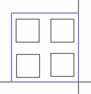
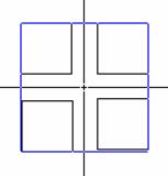
Example:
Define Special Tool
You have four center rectangles that
you want to define as a special tool. Select Define Special Tool
from the Special Tool submenu. Move into the work area. The system
prompts you to select the patterns you want to define as a special tool.
Move the crosshair to a point that is above and to the left of the four
rectangles. Click the left mouse button to start the marquee. Move the
crosshair down and right to enclose the patterns. When all the patterns
are enclosed within the box, click the left mouse button.
Selecting the patterns for
the special tool.
The
system now prompts you for the center point. Press <Enter> to accept
the default center point, or input the X and Y Offset coordinates and
press <Enter>. Click the right-mouse button to complete the operation.
The Define Special Tool window appears.
Selecting the center point
for the special tool.
When you have
selected the patterns and specified the X/Y Offset for the special tool,
the Define Special Tool window appears. The preview pane to the right
displays a thumbnail image of the selected patterns.
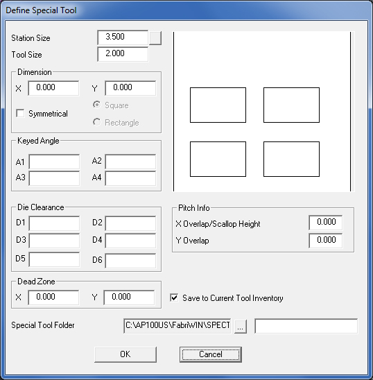
Option |
Description |
Station Size |
Type the station size required
for the tool. |
Station Size Toggle Button |

|
The toggle button next to
the Station Size text box allows you to toggle through the available
keyed or auto-index station sizes of the currently loaded turret.
The software will analyze the overall size of the patterns and
automatically select the next largest station size, but you can
also type a new value in the Station Size text box to overwrite
the calculated value. |
Tool Size |
The software automatically
calculates the tool size according to the overall rectangular
zone of the selected patterns from the center origin or X and
Y offset. You cannot edit this value. |
Dimension (X and Y) |
You can record an X and Y
dimension (X is the smaller dimension; Y is the larger) for the
tool. |
Symmetrical |
If you enable Symmetrical,
you can specify whether the tool reacts to angles like a square
or rectangular tool. |
Square |
If you select Square, you
could assign the tool to patterns having the same direction, but
at different angles. For example, 0°, 90°, 180° and 270° would
be the same direction to a square tool. As long as the special
tool is in the turret at one of specified angles, it can also
be assigned to any other special tool that was at 90° intervals. |
Rectangle |
If you select Rectangle,
you could assign the tool to patterns having the same direction,
but at different angles. For example: 0° and 180° would be the
same direction, as would 90° or 270°. |
Keyed Angle (A1-A4) |
Use the text boxes, A1 to
A4, to record up to four angles at which the tool can be keyed. |
Die Clearance (D1-D4) |
Use the text boxes, D1 to
D4, to record up to four die clearances. |
Dead Zone (X and Y) |
Dead zones indicate the safety
area reserved around each tool within the system will not punch.
The values are half of the desired overall dead zone. Type the
dimensions in the X and Y text boxes. |
Save to Current Tool Inventory |
If there is a check mark
in the Save to Current Tool Inventory check box, the system
adds the special tool to the currently loaded Tool Inventory. |
Special Tool Folder |

|
The system saves the special
tool to the default \Spectool folder, but you can click the navigation
button to the right of the path information to choose an alternate
directory or new setup directory. |

|
To save the special tool
that you have defined, click in the File Name field and type a
name for the special tool. The system will automatically add the
*.spt filename extension. |
The Define
Cluster Tool Array… option on the Special Tool submenu allows
you to determine the center points of cluster tools (more than two tools
in a group) to generate perforated sheets or part areas. This option allows
you to select a pattern set, define a special tool from that set, and
then search the part or sheet for identical cluster patterns. The system
then assigns the tool as a single hit and continues to search for matching
patterns.
You can use
two methods to define a cluster tool array. You can select a pattern array,
define it as a special tool, and then have the system apply it to the
patterns. The other method involves the system searching for array patterns
and assigning an existing special tool.
Notes: As a rule, the system
attempts to apply the special tool to the array according to the Horizontal
or Vertical options in the Define Cluster Tool Array window. The software
essentially ignores any irregular shapes, thereby reducing the amount
of processing time.
When prompted to select the cluster
array area, the patterns in the array must match those of the special
tool.
The system displays the “No cluster
patterns match selected area” message if it cannot find any matching patterns
during the first search path.
If there are common distances
between the centers of the special shape, the system will group the pattern
as a pattern line, otherwise, a single hit placement is assigned to the
grouped special tool.
The system displays a message when
it completes the processing of the cluster area.
The options in the Define
Cluster Tool Array window allow you to select cluster array patterns
to define as special tools, and then assign the selected patterns
as tools, or assign a previously defined special tool to a pattern
array. |

|
Option |
Description |
Search Path |
Use the options in this section
to specify the search path. |
Horizontal |
Select Horizontal if you
want the system to search for matching cluster patterns horizontally
row-by-row. |
Vertical |
Select Vertical if you want
the system to search for matching cluster patterns vertically
column-by-column. |
Preview Pane |
The Preview Pane to the right
of the Search Path options displays a thumbnail image of the selected
cluster array or of the currently selected special tool. |
Patterns to Use for Cluster |
Use the options in this section
to choose the selection method. |
Pick Patterns |
Select this option if you
want to draw a rectangular marquee around the patterns. The Box
Area and Fenced Area options become available. |
Use Special Cluster Tool |
Select this option if you
want to use the previously defined cluster tool or to choose an
alternate cluster tool for the array. |
Angle |
Special Cluster Tool can
now process pattern array with this given angle
|
Path Information |
This field displays the current
path and filename for the cluster tool. You can click the navigation
button to the right and select an alternate cluster tool to apply
to the array patterns. |
OK |
Click OK to begin the selection
process. |
Cancel |
Click Cancel to exit the
Define Cluster Tool Array window. |
Box Area |
Click Box Area to draw a
rectangular marquee around the patterns you want to define as
a special cluster tool. |
Fenced Area |
Click Fenced Area to draw
a freehand rectangular marquee around the patterns you want to
define as a special cluster tool. Make sure to snap the end point
of the last line to the start point of the first line to complete
the fence. |