While in the Turret Window>Tool Inventory Panel with the Add New Tool panel or Edit Tool panel open, the user can specify the shape, dimension, angles and clearances for a tool.
Double-clicking a tool in the Tool Inventory panel will open the Add New Tool / Edit Tool panel. Click the Info… command button to display the Tool Information dialog. Specify supplementary information for each tool and customize the tool inventory.
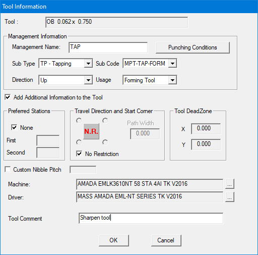
Tool
This read-only field only displays the name of the selected tool.
Note: Certain options are enabled only when using 2016 or newer drivers.
Management Name
Text entered directly into the field becomes the Management Name for the tool, which will appear in the Management No. column in the Used Tooling tab in the Process Information window. Enter a maximum of six characters.
The Management Name is passed to the SDDJ used tool list for that program.
Note: Accessible only to SDDJ users.
Punching Conditions
Click to open the Punching Conditions dialog to attach conditions to the tool.
Sub Type
Select what type of tool it is -
CP
- Center Punch
BR - Extrusion
TP - Tapping
SE - Forming
KI - Marking
Sub Code
If
TP - Tapping is selected,
Sub Code choices are -
Tapping II, Tapping Unit, Tapping Tool, MPT-TAP-CUT, MPT-TAP-FORM
For more info see Tapping
Tool Info.
If SE - Forming is selected, Sub Code choices are - NOT KEYED, KEYED, SLOT II, Deburring SQ/RE, Deburring RO, Slotting III
If KI Marking is selected, Sub Code choices are - NOT KEYED, KEYED, SLOT II, Deburring SQ/RE, Deburring RO, Slotting III
Direction
Specify the direction of the tool - Up or Down.
Usage
Select how the tool will be used - Forming Tool, Pierce Punch Tool, Perimeter Cut Tool, Nibbling Tool, Skeleton Cut Tool, Final Cut Tool, Separation, Punch Out.
Add Additional Information to the Tool
Check this option ON (as in the image above) in the Tool Information dialog to enable the following options.
Preferred Stations
If you have preferred stations for some of your tools, use this section to record the station numbers. To use a Preferred Station, you must also specify a machine name in the Machine: text box. Preferred stations are only used during tool selection when the current machine name matches the name specified in the Tool Inventory.
None
Select None to place the tool
in the first available station of its size.
First
Use First to specify your preference
for the first station in which the system should attempt to fit
this tool. Remove the check mark from None and then type a station
number in the First text box.
Second
Use Second to specify your preference
for the second station in which the system should attempt to fit
this tool. Remove the check mark from None and then type a station
number in the Second text box.
Travel Direction and Start Corner
Use the Travel Direction and Start Corner options to define the direction that Auto Sequence should use when sequencing this tool for code generation. Click the Sequence Direction indicator graphic to toggle through the various sequence direction options.
Travel Direction
![]()
No Restriction The system will sequence the tool using the shortest distance from the last pattern sequenced.
![]()
Line-By Line X Use
this option to sequence the tool along the primary X-axis, return
to the original starting edge, and then sequence the tool along
the closest pattern off the primary axis from the last sequenced
pattern.
Note: AP100US supports setting tool travel direction to Line by
Line for a special tool.
![]()
Line-By-Line Y Use this option to sequence the tool along the primary Y-axis, return to the original starting edge, and then sequence the tool along the closest pattern off the primary axis from the last sequenced pattern.
![]()
X-Axis Use this option to sequence all patterns in the X direction before moving along the Y-axis.
![]()
Y-Axis Use this option to sequence all patterns in the Y direction before moving in the X direction.
No Restriction
Check this box if you do not want to restrict the starting corner during sequencing. Remove the check mark to enable the four start corner options.
Start Corner
Select one of the four Start Corner option buttons that surround the Sequence Direction indicator graphic to determine where the sequencing should begin. (No Restriction must be unchecked to use this option.)