![]()
Tapping Tool (see Scribing Tool)
Step 1 - The user will need to select a tool from the inventory that will be used for the Tapping Tool. Although any Tool Type can be used, the most probable type will either be Round or Special. For this example we will use a Round Tool for the pilot hole and a Special Tool for the Tapping Tool. The illustration below displays the upper portion of the Tool Information window for both tools.

The window on the left is for the Pilot Hole. Since this is a standard round tool there is no Management Information needed. The Management Name is optional and in this example RO136 is used. The window on the right is for the Tapping Tool. Since we are using a special tool the Name of the tool appears in the Tool box. The Management Name is set to TP832 with the Sub Type set to TP (Tapping), and the Sub Code set to MPT-Tap Cut. The software will pass the proper values to the 3 Tool Conditions “96SUB TYPE”, “96SUB CODE”, and “96USAGE”.
Step 2 - After the Management fields have been set, the user can set Punching Conditions to the tool. The illustration below displays the Punching Condition window for each tool.
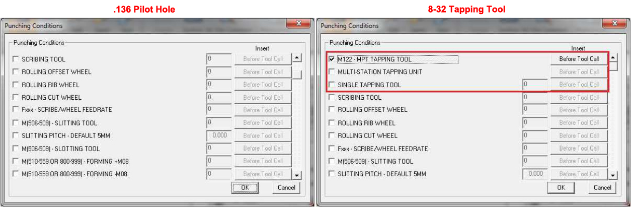
The Condition window on the left was selected with the standard Round Hole and the window on the right was selected with the Special Tool set to TP (Tapping) Sub Type. The window on the left starts with SCRIBING TOOL and the window on the right has 3 TAPPING items before SCRIBING TOOL. This is due to the TOKEN setting in the driver source. Here is how it will work:
RO 0.136 = SUB TYPE set to Blank Space which passes 0 to Sub Type Condition.
TAP 8-32 = SUB TYPE set to TP Tapping which passes 3 to Sub Type Condition.
The Tool Conditions for the Tapping items are setup as follows.
SetSpecFormat (STANDARD_CODE,"93M122 MPT TAPPING","MPT
TAP TOOL");
SetSpecFormat (STANDARD_CODE,"93MULTI-STATION TAPPING
UNIT","MULTI-STATION");
SetSpecFormat (INPUTDATA_INT_CODE,"93SINGLE TAPPING TOOL
","SINGLE TAP");
The setting for each of the Tapping Punching Conditions is set to 93. The 9 is for Tool Condition and the 3 is the TOKEN that will be used to check the tool SUB TYPE. This means that the Tapping tool conditions will only be displayed if the tool' Sub Type Condition is equal to 3.
RO 0 -.136 Sub
Type = 0 - Displays all Conditions that are “9...” or “90...”.
TAP - 8-32 Sub
Type = 3 - Displays
all Conditions that are “9...”,
“90...” or
“93...”.
Step 3 - After
all of the data has been passed to the driver, the driver will be able
to output more information for each tool in the AMNCF Header. The
3 Punching Conditions “96SUB
TYPE”,
“96SUB
CODE”,
and “96USAGE” will contain
a variable that will be used to store the value that is passed from
the software. This variable will be updated for each tool so that
the proper data can be output to both the AMNCF Header and the UTL
file. The sample below displays how the RO
0.136 and TAP
8-32 will be output to the AMNCF
header using the Management Information.
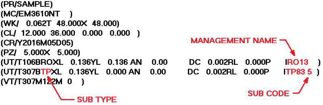
The sample above displays the locations for the different Management items. With the information that is passed from the Management fields, the driver and UTL files will have complete control over the output.
Scribing Tool
Step 1 - The user will need to select a tool from the inventory that will be used for Scribing. This example will use a Round too for scribing and a standard Rectangle Tool for the boundary. The rectangle is to show how the Usage field will be used. The illustration below displays the upper portion of the Tool Information window for both tools.

The window on the left is for the .031 Round and the window on the right is for the .250 X 4.000 Rectangle. The Round tool will be used for Scribing so the Sub Type is set to KI Marking, and the Sub Code is set to Contouring. The rectangle tool will remain a standard tool with no Sub Type or Sub Code, but the Usage will be set to Perimeter Cut Tool. Since this tool is used for the part boundary, the usage command will pass the Perimeter Cut value for the proper code (O) to be output in the AMNCF Header.
Step 2 - Again after the Management fields have been set, the user can set Punching Conditions to the tool. The illustration below displays the Punching Condition window for each tool.
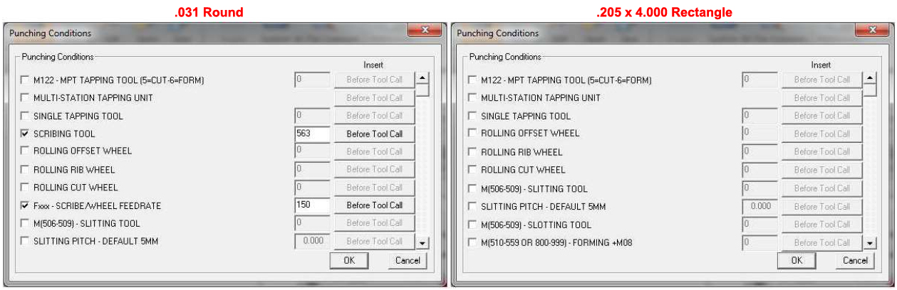
The Condition window on the left was selected with the Round Hole set to KI (Marking) Sub Type and the window on the right was selected with the Rectangle Tool. The window on the left contains all of the Condition items while the window on the right is missing the SCRIBING TOOL and Fxx - SCRIBE/WHEEL FEEDRATE Conditions. This is due to the TOKEN setting in the driver source. The tools below display the settings and how it affects the Condition list.
RO 0.031 = SUB
TYPE set to KI
- Marking which passes 5 to
Sub Type Condition.
RE 0.250x 4.000 = SUB
TYPE set to Blank
which passes 0
to Sub Type Condition.
The Tool Conditions for the Scribing items are setup as follows.
SetSpecFormat (INPUTDATA_INT_CODE,"95SCRIBING
TOOL","SCRIBING TOOL");
SetSpecFormat (INPUTDATA_INT_CODE,"95Fxx SCRIBE/WHEEL FEEDRATE","FEEDRATE");
The setting for each of the Scribing Punching Conditions is set to 95. The 9 is for Tool Condition and the 5 is the TOKEN that will be used to check the tool SUB TYPE. This means that the Scribing tool conditions will only be displayed if the tool' Sub Type Condition is equal to 5.
RO 0.031 -
Sub Type = 5 - Displays all Conditions that
are “9...”,
“90...” or
“95...”.
RE 0.250x 4.000 Sub Type
= 0 - Displays
all Conditions that are “9...”
or “90...”.
Step 3 - After all of the data has been passed to the driver, the driver will be able to output more information for each tool in the AMNCF Header. The 3 Punching Conditions “96SUB TYPE”, “96SUB CODE”, and “96USAGE” will contain a variable that will be used to store the value that is passed from the software. This variable will be updated for each tool so that the proper data can be output to both the AMNCF Header and the UTL file. The sample below displays how the RO 0.031 and RE 0.250x 4.000 will be output to the AMNCF header using the Management Information.
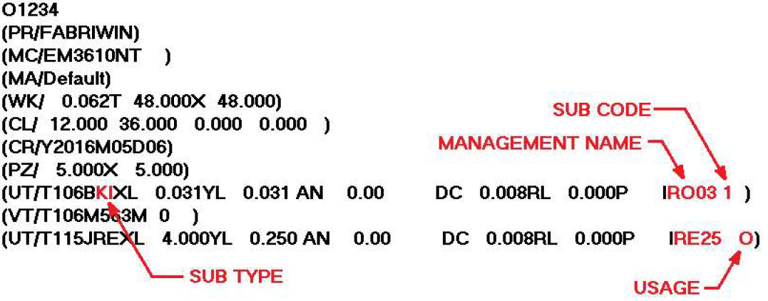
The sample above displays the locations for the different Management items. With the information that is passed from the Management fields, the driver and UTL files will have complete control over the output.