Options covered on this page -
The manual tool selection options allow you to decide which tool to assign to a pattern. You can assign tools directly to patterns, place tools in specific turret stations, and determine which tools have been assigned to the patterns. Use the manual tool selection options in Sheet or Part view.
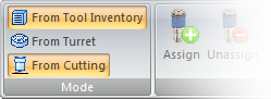
Notes: Determine whether you want to select tools from the Tool Inventory, From Turret or From Cutting and make sure to check the Nibble On setting.
For a punching system, you can use the From Tool Inventory or From Turret options. If you select From Tool Inventory, the Tool Inventory flyout window will filter the Tool List and display only those tools in the inventory that match the station sizes of the currently loaded turret. If you select From Turret, the Tool Inventory flyout window will only list the tools currently loaded in the turret.
For a combination system, you can use the From Tool Inventory, From Turret or From Cutting options. If you have From Turret and From Cutting enabled, the system will display the Combo Tool Assignment dialog when you select the Assign option from the Tool menu. Select From Tool Inventory, From Turret or From Cutting and then click OK. You can then make the tool assignment.
Parts can overlap on complex sheets. These types of sheets require special techniques during manual tool selection:
Most tool selection problems occur in Sheet view when patterns are small or difficult to see and therefore difficult to select. Try magnifying the view or switching to Part view.
Make sure you know what highlight color the system is using for assigning tools when the pointer obscures rounds and lines. When the crosshair covers an entire line, sometimes the highlight color appears in a different shade. To check this, move the pointer to the center of a round; this is the normal tool highlight color. Now move the pointer to the center of a line; this is the tool highlight color for a pattern obscured by the cursor.
If snap points are active, use the right mouse button to toggle between patterns when the cursor rests on the intersection of two patterns. To toggle between patterns with Snap Mode off, use the <Tab> key.
If you have overlapping parts, and with the snap points on, the system selects the active part first. Press the <Space Bar> to toggle to a second part.
Try disabling snap point mode and then use the right mouse button to snap to the pattern before pressing the left mouse button to select it. This also helps with overlapping parts. You can use the <F3> key to turn on the part boundary display.
To select small patterns at the edge of a part, try moving the cursor from inside the part boundary slowly out to the edge. If you still encounter difficulty, press <F2> to turn off the snap point mode and use the right mouse button to snap to the pattern.
Important! Viewing tool hits has nothing to do with the punching order. The display of the tool hits allows you to see the entire sheet with all the tool assignments. You can then determine if all patterns have tool assignments and which tools are used. Use the Punch Sequence options to determine the punching order.
You may want to alter the Viewing Speed to set a default redraw speed.
![]()
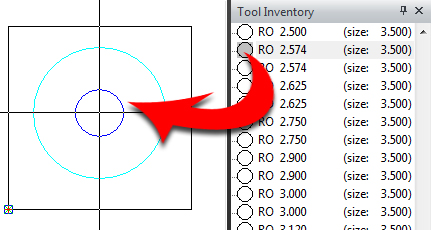
The Assign option allows you to select the tool to use on a pattern. You can also change tools selected by Auto Part or Auto Sheet. Click the icon, drag in a suitable tool from the Tool Inventory and click in the pattern to place the tool. The Round tool being assigned to this pattern will nibble out the Round pattern.
If a tool a new tool is dragged in and assigned to a pattern that already has a tool, and no other pattern on the sheet uses that tool, the system removes the existing tool from the turret. To avoid removing tools from the turret, use the Unassign Tool option before assigning a different tool. When a new tool is assigned to a pattern in one part on a gridded sheet, that new tool will appear on all copies of the part.
Note: If From Tool Inventory is selected, the system places each tool assigned in the turret.
Locked Patterns
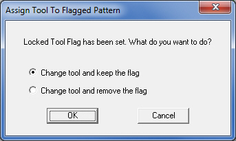
When attempting to assign a tool to a pattern that has been locked, the system will prompt for further action. The user may choose the Change the tool and keep the locked pattern property, or change the tool and remove the locked flag from the pattern. (See Assigning Locked Tool Flags.)
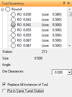
When you use the Assign option, the Tool Inventory properties window will appear. The fly out window will list the tools you can apply to the patterns. You can determine the station assignment and size, and choose the angle and die clearance for the tool.
Note: When assigning Special Tools to a part from a Tool Inventory or placing (special) Tool Hits, any Special Tools from the Tool List which do not have an *.SPT file in the Special Tool folder will be grayed out.
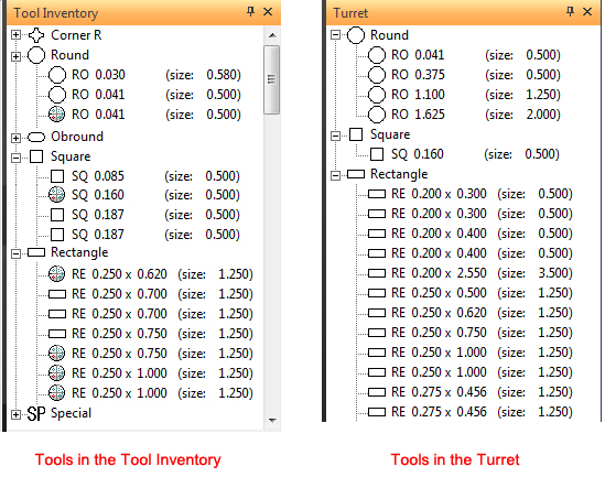
Tool List
The Tool List in the Tool Inventory window will display the tools that are in the currently loaded tool inventory. If you have selected From Turret on the Tool menu, the Tool List will display the tools currently loaded in the turret stations.
Station
In the Tool Inventory window a navigation button appears next to the Station label if a selected tool has not yet been assigned. Click the button to assign the tool to a specific station in the turret. The Stations Available dialog will list all the empty stations that are that are suitable for the selected tool. Click the desired station and then click OK. Move the pointer into the work area and assign the tool.
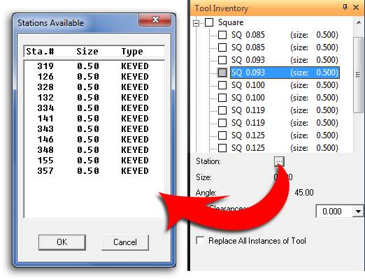
Note: If the tool you are assigned has a preferred station, that station is selected (highlighted) when the Station Available window appears. You can click OK to use the preferred station or select a different station and click OK.
The Size indicator will display the size of the selected tool in the Tool List.
Station Angle
The Angle list allows you to view and select the tool angle. If the tool is in the turret, the current value that appears in the Angle text box is the installation angle. If the tool is not in the turret, all the angles that you defined for the tool in the Tool Inventory will appear in the Angle drop-down list.

The Die Clearances pull-down list allows you to view and select the die clearance. If the tool is in the turret, the value the tool is currently using will appear in the Die Clearances text box. The remaining die clearance values that you defined for the tool in the Tool Inventory are available in the drop-down list. You can select the desired value. The selected value will be applied to that station.
If the tool is not in the turret, the value that appears in the Die Clearances text box is the first die clearance that you defined for the tool in the Tool Inventory. The remaining die clearance values are available in the drop-down list. You can select the desired value from the list and then assign the tool to a pattern. The system will place the tool in the correct station. The selected value will be set as the current die clearance for that station.
Click for more info on die clearances.
When placing a tool assigned to a pattern with a new tool, this option allows you to assign the substitute tool to all the patterns that use the tool being replaced. When this option is enabled, the Put in Same Turret Station option also becomes available.
Put in Same Turret Station
This option allows you to place the new tool to be assigned in the same turret station as the one being replaced. Note: This checkbox displays when Replace All Instances of Tool is checked ON.
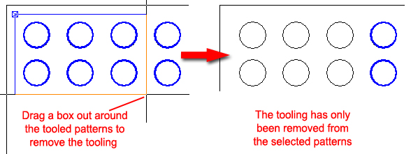
Unassign Tool / Box Unassign Tools


Select Unassign and click on any single tooled pattern to remove the tool. This will not remove the same tool that may be assigned to other patterns on the same part; the tool will only be removed from the pattern selected. If there are other similar parts that are gridded, the tool selected for Unassign will be removed from every part.
The user may also select Box Unassign from the pull-down menu, drag out a box around adjacent patterns and left-click to finalize the box and remove tooling from the selected patterns.
![]()
The Clear option on the Tool menu removes the tools from all the patterns on the part or sheet; however, the tools will remain in the turret. When a punching machine is installed, the first dialog will display. Click Yes to clear tooling.
![]()
If a combo machine is loaded the user must choose between clearing Punching Tools, Cutting Tools or both in this dialog. Select tooling types and click OK to clear the tools specified.
If there are any locked tool flags assigned (including irremovable tools), select Clear all tools including locked tools and then click OK to remove all the tools and those tools assigned to patterns with locked tool flags. To remove all tools except those that are locked, select Keep the locked tools and then click OK.
![]()
If you are dissatisfied with the results after performing a tooling operation, select the Undo option and the last action is reversed. You can also press <F8> to reverse the last action. (See Undo/Redo.)
![]()
If you want to repeat a tooling operation that you reversed using the Undo command, select Redo and the last action is restored. You can also press <F9> to restore the last action. (See Undo/Redo.)
![]()
The Inquire option allows you to determine the tool assignment for a pattern. You can then determine if the punch or sequence is good for the pattern. Select Inquire from the Tool menu and move into the work area. Click the pattern you want to query. The image of the tool appears, and its name, station, size and angles appear in the Tool window. You can inquire any or all the tools in the work area.
Notes: This option remains active until you select another option. A check mark appears next to the command in the Tool menu to indicate that it is active.
If you inquire a pattern that has no tool assignment, the word NONE appears in tool name field of the Tool window. If the pattern is designated as cutting, then CUTTING appears in the tool name field.
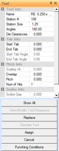
The Tool window appears when you select the Tool>Inquire option and click on an assigned tool in the work area. The tool name, station number, size, angles and die clearances appear in the top portion of the window. In addition, there are options for tabs, pitch info, tool replacement and scribe info. |
|
|
|
Option |
Description |
Tool Info These read-only fields display general tool information. |
|
Name |
The name of the tool displays in this field. |
Station # |
Displays the station number. |
Station Size |
Displays the station size. |
Angles |
Displays the available angles for the tool. |
Die Clearances |
Displays the available die clearances for the tool. This field is editable from the drop-down list if other clearances are available for this tool. Die Clearances must be added when the tool is created or edited. See Creating and Editing Tools for more info. |
Tab Info The options in this section display editable tab information for a tool.= |
|
Start Tab |
Enter a starting tab value for the tool. |
End Tab |
Enter an ending tab value for the tool. |
Start Tab Angle |
Enter a starting tab angle for the tool. |
End Tab Angle |
Enter an ending tab angle for the tool. |
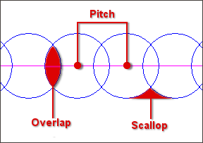
Pitch / Overlap / Scallop Info These options allow various tool hit characteristics of the inquired tool to be edited. These options are all interconnected; editing the values in one field automatically updates the others.
|
|
Scallop Height |
This is the height of the scallop formed by nibbling tools. Note: This field is disabled when a rectangle or square is inquired. |
Overlap |
The amount that tool hits overlap for the currently inquired tool. Note: This field is disabled when a round or obround is inquired. |
Pitch |
The distance between the centers of adjoining tools. |
Num of Hits |
The number of times the tool punches - or hits - when nibbling. |
Cutting Replace Info |
Select Replace All Instances of Tool to replace all instances of the tool currently assigned to the patterns with a new tool selected from the Tool List. |
Scribe Info |
Use the Scribe Gap option to control the pitch between hits for a designated scribe tool. Changes made here will be reflected in the Pattern Properties - General (Line) panel. |
Function Buttons |
|
Show All |
Click Show All to refresh the display and to view all the tool hits for the currently inquired tool. |
View/Modify Tool Sequence |
Click View/Modify Tool Sequence to view the current sequencing for the tool or to edit the sequencing for the tool. See Tool Sequence Priority Window. |
Replace |
Click Replace to assign a substitute tool to all the patterns that use the tool that you want to replace. |
Reorder Tool |
Click Reorder Tool to view and edit the sequence priority of the tools. See Tool Sequence Priority Window. |
Assign |
Click Assign to apply the replacement tool to the patterns. |
Cancel |
Click Cancel to exit the Tool window. |
Punching Conditions |
Click Punch Conditions to view and edit the punching conditions that are assigned to the currently inquired tool. See Punching Conditions Dialog. |
For information on these options, refer to the Line Side, Direction & Tabs page.
![]()
The Fence Auto Assign function allows the user to define any shaped closed-boundary area that will be the target for Auto Tool Assignment. Tool Assignment will draw tools from the currently loaded Tool Inventory and the Fence Selection will occur as soon as the user left-clicks a final time to close the selection boundary. When drawing out the fence, the user must left-click to place Fence Select Points as shown below, right-click to close the fence and left-click again to finalize.
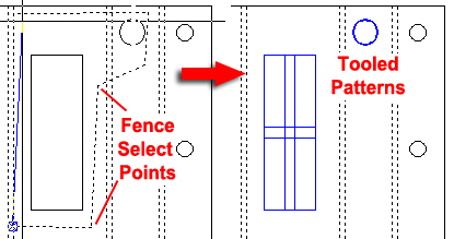
Notice that only the selected patterns (shown in blue) have been tooled
Tool Line Nibble![]()
The Tool Line Nibble option on the Tool menu allows the user to manually apply a nibble tool along the part boundary. The software will draw a line according to selected start and end points and then automatically apply a tool to that line. The tool is selected according to the Tool Assignment preferences you have defined for Lines.
Notes: It may be necessary to check your Tool Assignment preferences for Lines in the Preferences>Tool Assignment panel.
Use the same methods for drawing the line punch-outs as you would for a construction or solid lines. You can type coordinates, use Snap Mode, Step Mode or the IntelliSnap feature to select the start point and end point for the line. The system will not auto-fit tools to the remaining patterns when you use the Tool Line Nibble option.
How to apply Tool Line Nibble
Select Tool Line Nibble from the Tool menu and then look through the Tool List in the Tool Inventory window and select an appropriate tool (in this example a Rectangle was selected). To precisely place the tooling line on the corners of the part, move the crosshair cursor near the corner of the part and right-click to snap to the corner, then left-click to start the line. Repeat this on the opposite corner and the tools will auto-assign.
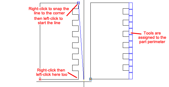
Note: Be sure that Snap Mode in Preferences>Display Options is checked ON.
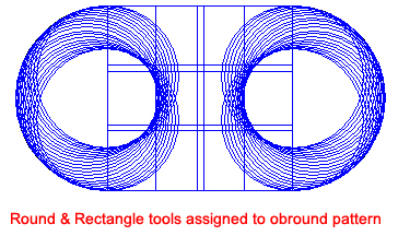
![]()
This option allows the user to assign more than one tool to a single pattern. The pattern must be a Round Hole, Rectangle Hole, Center Rectangle, Rounded Corner Hole or Obround Slot. Select Assign Multiple Tools from the Tool menu, and then select the pattern. The system automatically selects the tools from the inventory or turret, depending on user preferences.
Notes: The Assign Multiple Tools feature is unavailable during auto-tool assignment.
If you unassign one tool, the software will remove all the tools placed on the pattern using Assign Multiple Tools.
When one of the tools is re-assigned, the remaining tools (if necessary) are automatically re-assigned. For example, if the smaller perimeter tool that is assigned to a round pattern is re-assigned, the larger center tool becomes invalid and is automatically re-assigned.
Note: An error message will appear if the system cannot assign multiple tools to a pattern.
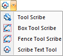 |
The Tool Scribe option on the Tool Assign tab allows the user to select a group of lines and arcs, and assign a scribing tool to the paths. The Scribe Text Tool option allows the user to generate an etch path and assign a scribing tool to the text. The Scribe/Etch Text window allows you to define the parameters for a block of text and place the text on a pattern in the work area. See Scribe/Etch Text Window. For more info see Scribing Tool Info. |
|
Note: When applying the scribe tool, the software will update the line or arc side properties. The tool will scribe directly on the center of the line or arc. There will be no left or right side compensation.
|
Choose a Scribe Tool |
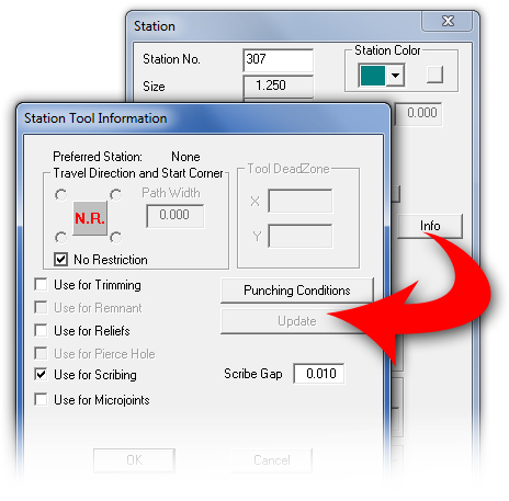
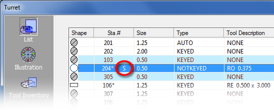
To begin with, one or more tools in the turret must be designated as a scribing tool. Open the Turret-List window and double-click the row in the list containing the tool you want to designate as a scribing tool. When the Station window opens, click the Info button to open the Station Tool Information window as shown in the image below. See Machine>Turret Window - List View for more info.
|
|
Place a check in the Use for Scribing checkbox to select that tool as a scribing tool. When the box is checked the Scribe Gap field is activated. The Scribe Gap value must be set to control the gaps between tool hits of the Scribe Tool. The Gap Value should be greater than 0. Note: The Gap Value takes effect when assigning scribe tool manually, not when using Auto Part or Auto Sheet, even IF the option Use for Scribing has been checked.
|
|
When a scribe tool has been selected, click OK in Station Tool Info and close the Station window. The letter "S" now displays in the Station #204 row, indicating that this tool will be used for scribing.
|
Apply the Scribe Tool |
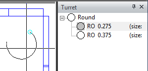
To apply the scribe tool to a pattern, click the Tool Scribe option. When this is done, only scribe tools will display in the Turret list as shown here -
Select the tool in the Turret list and then drag it into the work area. When the cursor/crosshair is near a pattern it will snap to it. Click on each end and then in the center of the pattern, then refresh the screen (roll the center mouse button) and the pattern is tooled. The user may also apply scribe tools using the Box Tool Scribe or Fence Tool Scribe options in the Tool Scribe menu. Drag a box or draw a fence to select the patterns and the selected scribe tool will be assigned. Note: It's not possible to assign a scribing tool to a closed boundary pattern (such as a Round Hole). First the pattern must be exploded into an open boundary pattern (ex: the Round pattern will become a 360o arc). See Draw>Edit>Exploding and Splitting Patterns.
|
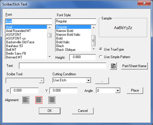
The Scribe Text Tool option allows the user to specify the properties for the text to be etched or scribed, assign a scribing tool to the patterns, and place the text in the work area. When you select the Scribe Text Tool the Scribe/Etch Text window appears. In this window enter and configure the text as desired and select a scribe tool. The user may also click Part/Sheet Name to insert the name of the current part or sheet into the Text: field. |
||
|
||
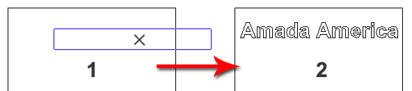
Note: Using complicated True Type fonts can add a lot of extra geometry, etching time and code. With the default Use Simple Text option checked ON, the program will automatically choose a Simplex font when scribing and etching. When the text is ready, click the Place button. The Scribe/Etch Text window will close and the text will appear as an outline box over the part as in image #1. Position the box on the part (right-click to change the angle) and then left-click to place.
Note: Clicking the OK button in the Scribe/Etch Text window causes the text to be placed according to values set in the X / Y text boxes. |
||
|
||
Option |
Description |
|
Font List |
The Font List displays all the fonts that are currently installed on your computer system. You can scroll through the list and select the desired font for the etch text. |
|
Font Style List |
The Font Style list allows you to apply a style, i.e., Regular, Italic, Bold or Bold Italic to the etch text. |
|
Sample |
The Sample area displays a thumbnail image of the selected font and font style. |
|
Height |
Type a value for the text height in this field. |
|
|
Note: Due to the many different styles of fonts, the actual vector reproduction may vary from the actual value you specify in the Height: text box. |
|
Use TrueType |
If you select Use TrueType, the system will assign the etch or scribe tool directly on the patterns consisting of TrueType fonts without any left or right line compensation. |
|
|
|
|
Use Simple Pattern |
If you select Use Simple Pattern, the system will use line compensation to generate contiguous line and arc patterns that are a simplified form of the TrueType font being used. |
|
|
|
|
Text Field |
Type the desired scribe or etch text in this field. |
|
Recall Button |
|
Click the Recall button or press <F3> to restore the any text that you previously typed in the Text: field. |
Scribe Tool |
Click the Scribe Tool arrow button and select a scribe or etch tool from the drop-down list. This list will only display those tools that you have designated as scribing tools. You must enable the Use for Scribing option in the Station Tool Information window to designate a tool as a scribing tool. (See Machine.) |
|
Cutting Condition |
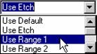
This option is available if you have a cutting or combination machine that supports cutting conditions for etching. The Cutting Condition list allows you to access the default, etching and range checking values that you defined in the material file. See Machine , Condition Tables Panel and Sequence Features, Etch Text. |
|
|
|
|
X |
The X coordinate of the etch text. |
|
Y |
The Y coordinate of the etch text. |
|
Angle |
You may select one of four angles from the Angle: drop-down list: 0, 90, 180 or 270. |
|
Place |
Click the Place button to manually position the text in the work area. A text box outline will follow the mouse pointer after you select Place. Move the text box to the desired position and click the left mouse button to place the text. |
|
Alignment |
The Left, Center and Right alignment buttons allow you to specify the origin output of the text. |
|
|
The text will be placed with the origin output to the left |
|
|
The text will be placed with the origin output to the center. |
|
|
The text will be placed with the origin output to the right. |
|
OK |
Click OK to place the etch text according to user-entered values in the X / Y text boxes, and to close the window.
|
|
Cancel |
Click Cancel to exit without placing the etch text.
|
|
|
|
|
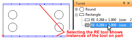
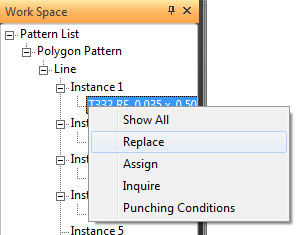
Right-click on a part, tool or pattern instance in the Work Space to display the flyout menu. The menus that display depend on whether the user is in Part View or Sheet View and the machine in use. Click Work Space for more info on the options in the various flyout menus.
![]()
When the From Tool Inventory option is selected as the Tool Selection mode, click the option and then in the Tool Inventory panel click on a tool. The selected tool will be hi-lited on the part (or parts) in the work area. When pulling tools From Turret, click on tools in the Turret panel. This option functions in both Part and Sheet View.