It may be necessary to adjust the line side, punching direction or tabs after the part or sheet has been tooled. The Change Line Side, Change Line Side - Scribe Path and Change Direction options allow the user to adjust the tooling relative to the side and direction of the line path.
The Tab, Tab Angle, Clear Punching Tabs and Stretch Tab options allow you to modify tabs placed on line and arc patterns.
![]()
When a sheet or part is tooled or sequenced, a pattern may punch on the wrong side of the line. To correct this problem, in the Tool Assign tab, from the Tool Assign sub-menu select Change Line Side and click a pattern to modify. Depending on the pattern, lines can be to the left, right, (top, bottom) or directly on the line. Arcs can be inside, outside or directly on the arc.
Note: If you change the line side for a grid pattern, you must use View Tool Hits to display the changes on the remaining parts. You can also edit the pattern in Part view to modify the line side. Continue to click the pattern until the line side appears correct.
It is possible to assign punching side preferences to individual patterns when drawing a part in Draw / Edit mode. See Draw>Draw Patterns>Line for an example.
The system passes the cutting side flag to the driver when generating NC code. Inside, Outside, and On use the “–1,” “1,” and “0” values, respectively.
If the cutting is on the inside of the pattern, the system will pass “-1” to the driver when generating NC code. But if the cutting is on the outside, the system will pass “1” to the driver. If the cutting is on the pattern, the system will pass “0” to the driver when generating NC code.
![]()
This option allows you to change the direction of punching for lines, arcs and radiused slots. Select Change Direction from the Tool Assign menu and click the pattern line that should punch in the opposite direction.
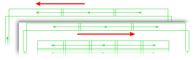
The
upper image shows the original sequence
In the bottom image the sequence is reversed
Note: Drawing patterns in a clockwise direction actually makes the pattern punch on the outside; drawing a pattern in a counter clockwise direction makes the pattern punch on the inside.
![]()
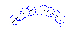
A tab is similar to a microjoint, in that it can keep the part attached to the sheet skeleton for easier sheet removal after processing. The Tab option on the Tool Assign submenu allows the user to add or modify tabs on lines, arcs or corner notches by lengthening or shortening the tool path.
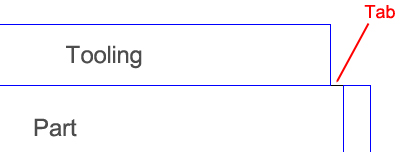
A positive tab value shortens
the tooling path and leaves a tab
Select Tab from the Tool Assign submenu and type a value in the Tab Size text box. A positive tab value shortens the tool path; a negative tab value lengthens the tool path.
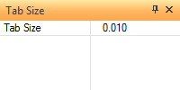
Tab size is typically
25% of material thickness
Move into the work area and click the end point of the pattern where you want to begin the tab. If you want to specify the same tab size for both ends of the pattern, click the center point of the pattern.
Notes: If you are adding a positive tab to a single tool hit, you can only place it on the starting point of the pattern. You may need to modify the direction of the pattern to achieve the desired results.
It is possible to assign tabs to part perimeters when drawing a part in Draw / Edit mode by using the Tab option. See Draw>Draw Patterns>Line for an example.
![]()
The Clear Tabs option on the Tool menu removes the tabs from all the patterns. Click Yes to clear all the tabs. After clearing tabs refresh the work area (roll the center mouse button) to see the patterns with tabs removed. This option cannot be undone.
![]()
![]()
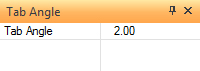
The Tab Angle option on the Tool Assign menu allows the user to add or modify tabs on arcs, which is measured in degrees. To use this option, select Tab Angle from the Tool Assign menu to specify the tab angle size. Type a value in the Tab Angle text box. A positive tab value shortens the tool path; a negative tab value lengthens the tool path. Press <Tab> to move ahead.
Move into the work area and click the arc you want to tab, and then click the end point of the pattern where you want to begin the tab. If you want to specify the same tab size on both ends of the pattern, click the center point of the pattern.
![]()
The Stretch Tab option on the Tool menu allows you to modify tab sizes and tab angles on a pattern-by-pattern basis. You can select any point on a pattern and drag the tool(s) along the moving path to adjust the tab size or angle. The snap points are activated and you can drag the tool(s) to adjust the tab properties. If necessary, you can use the Stretch Tab window to refine the tab parameters. (See Stretch Tab Settings Window.)
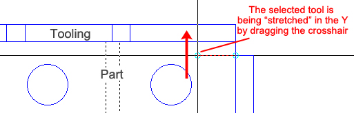
Notes: The Stretch to Edge and Stretch to Center options in the Stretch Tab Settings Window affect the Distance and Angle values. If you select Stretch to Edge, the Distance or Angle is calculated from the edge of the tool. If you select Stretch to Center, the Distance or Angle is calculated from the center of the tool.
The system will generate the tab size, but you can view or adjust the Distance or Angle value using the Stretch Tab window.
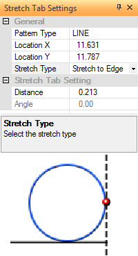
The Stretch Tab Settings window appears when you begin to adjust a tab along a tooled path. The options in this window allow you to refine the tab size and tab angle parameters. |
|||||
|
|||||
Option |
Description |
||||
General |
The general information appears in this section. |
||||
Pattern Type |
This field displays the selected path type: LINE or ARC. |
||||
Location X |
The X coordinate of the tab, measured from the part origin. |
||||
Location Y |
The Y coordinate of the tab, measured from the part origin. |
||||
New Location Buttons |
The New Location buttons allow you to move into the work area to relocate the tab size or tab angle location. |
||||
Stretch Type |
The options you can select from the Stretch Type drop-down list determine the calculation or X point |
||||
Stretch to Edge |
If you select this option, the tab size or tab angle is calculated from the outer edge of the tool. (See Location X Indicator.) |
||||
Stretch to Center |
If you select this option, the tab size or tab angle is calculated from the center of the tool. See Location X Indicator |
||||
Stretch Tab Setting |
Use the options in this section to adjust the tab value for lines or arcs. |
||||
Distance |
If you are adjusting the tab value for a line, select the current value and type a new value. |
||||
Angle |
If you are adjusting the tab value for an arc, select the current value and type a new angle. |
||||
The graphic in this section of the window will display the current Stretch Type setting. The tab size or tab angle is calculated either from the outer edge or center of the tool. The graphic provides you with a visual reference of the calculation parameter. |
|||||
|
|
||||