Option |
Description |
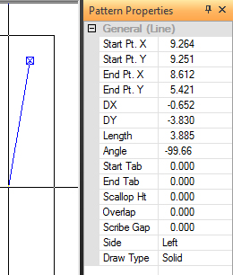
General
(Line) |
|
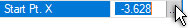
Start
Pt. X |
The X coordinate for the
starting point from the reference point of the part. Edit the
value by selecting the field and typing in a new value. Also,
when the field is hi-lited click the placement button that appears,
move the cursor into the work area and manually place the Start
point in x.
|
Start
Pt. Y |
The Y coordinate for the
starting point from the reference point of the part. Edit the
value by selecting the field and typing in a new value. Also,
when the field is hi-lited click the placement button that appears,
move the cursor into the work area and manually place the Start
point in y. |
End Pt.
X |
The X coordinate for the
ending point from the reference point of the line. Edit the value
by selecting the field and typing in a new value. Also, when the
field is hi-lited click the placement button that appears, move
the cursor into the work area and manually place the End point
in x. |
End Pt.
Y |
The Y coordinates for the
ending point from the reference point of the line. Edit the value
by selecting the field and typing in a new value. Also, when the
field is hi-lited click the placement button that appears, move
the cursor into the work area and manually place the End point
in y. |
DX |
The distance the line moves
in the X direction from its starting point. Edit the value
by selecting the field and typing in a new value. |
DY |
The distance the line moves
in the Y direction from its starting point. Edit the value
by selecting the field and typing in a new value. |
Length |
The overall length of the
line. Edit the value by selecting the field and typing in
a new value. |
Angle |
The angle of the line from
its starting point. Edit the value by selecting the field
and typing in a new value. |
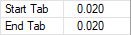
Start
Tab
End Tab |
The Start Tab text box allows
a tab to be specified for the starting point. To place tabs on
a line, move into the property window and edit the values for
the Start Tab (beginning of the line) or End Tab
(end of the line). To shorten the tool path or cutting path (make
the line shorter), use a positive number. To lengthen the tool
path or cutting path (make the line longer), use a negative number.
Note:
It may be best to wait and place tabs on individual part copies
after arranging the sheet. Tabs drawn on one part affect all the
copies made of that part. |
Scallop
Ht |
Type a value in the Scallop
Ht. text box to specify the scallop height for the line. The scallop
height is the distance formed by the scallop created by nibbling
tools. See Pitch/Overlap/Scallop
Info. |
Overlap |
The value in this text box
allows the user to control the distance between tool hits along
the length of the line. |
Scribe
Gap |
Use the Scribe Gap option to control the
pitch between hits for a designated scribe tool. Changes made
here will be reflected in the Tool
Info panel. |
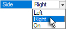
Side |
Change the side of the punched
line while adding or editing a pattern. Move into the property
window and select the Side option of your choice from the
drop-down list: Left, Right or On.
Learn how to use the Change
Line Side option on the Tool menu (punching) or Change Side on
the Cut Sequence menu (cutting) to change the line side after
assigning punch or cutting tools. When shearing or punching a
line, specify which side to cut or punch. When shearing or cutting
around the part in a clockwise direction, the line is processed
on the left side. When shearing or cutting around the part in
a counter-clockwise direction, the line is processed on the right
side. It functions like the positive and negative values of the
NC code; the left side is positive and right side is negative. |
Draw
Type |
The Solid and Construction
options control whether the line appears as a solid line (one
to cut or punch) or a construction line (for bending or reference
only). Construction lines appear as dashed lines. Use a solid
line for cut or punched patterns. |
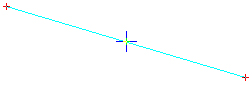
Line
Snap Points |
Once a line has been drawn
out, edit by clicking the Edit button.
When a line is ready to be edited, it will have three snap points:
one at the beginning, one in the center and one at the end.
|