The options in the Tool Assignment panel allow you to define the Auto Tool Assignment parameters. The software uses these values to automatically select the tools for the patterns on your part or sheet. You can modify them to reflect your personal preferences.
Option |
Description |
|
The options contained in this section allow you to control what type of tools will be assigned during the Auto Part or Auto Sheet tooling process. The software will determine the best solution for the automatic tool assignments according to the specified order in the Tool Priority list. The software will determine the best solution for tool assignments according to the selected pattern type in the Pattern List section, and the selected order in the Tool Priority list. (See Auto Tool Assignment Priority for more info.)
|
||
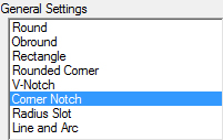
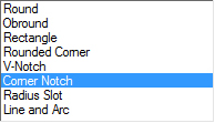
To specify the assignment preferences, select a pattern type: Round, Obround, Rectangle, Rounded Corner, V-Notch, Corner Notch or Radius Slot. When Line and Arc is selected, the Tool Priority list changes to Line and Arc options. (See Line and Arc for more info.)
|
|
|
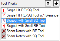
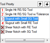
This table displays the default priority for each auto-tool assignment. (See Auto Tool Assignment Priority.) When a tool is selected in the list, a small thumbnail of the tool hits displays.
|
|
|
Restore Current |
Restore the default tool assignment priority for the selected pattern type in the Pattern List.
|
|
Restore All |
Click Restore All to restore the default tool assignment priorities for all the pattern types in the Pattern List.
|
|
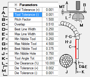
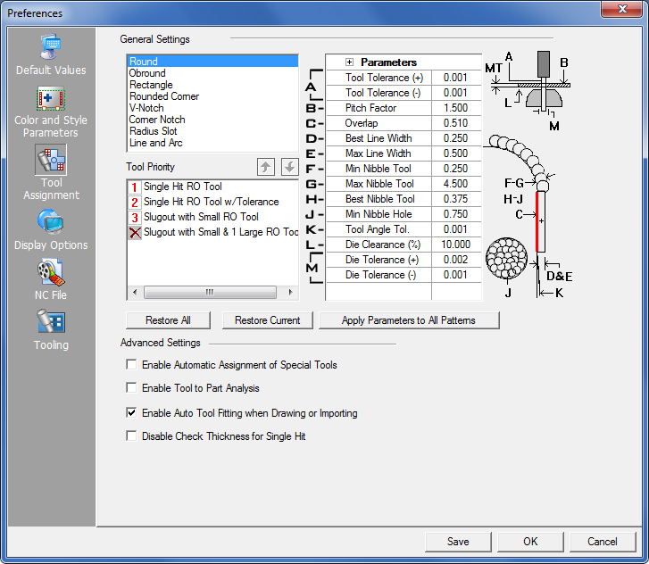
| The Parameters table allows you to define the conditions the software uses for tool selection. To modify a value, highlight the corresponding label and enter the desired value. | ||
|
|
The
diagram shown at the right of the Parameters table indicates the
area or object that is affected when a value is changed.
For example, a value entered in row J (Min Nibble Hole) will control the minimum size of a hole that the system will automatically nibble out (shown by the J diagram). |
|
Tool Tolerance (+) - Tool Tolerance (-) These two options instruct AP100US to automatically select a tool that falls within the specified range. For example, if a pattern, part or sheet is not exactly the same size as a tool as that in the inventory, the system selects the tool that most closely matches the specification. If you have the tool tolerances defined as + 0.003 and – 0.001, and you have a 0.188” diameter round hole drawn on the part, the system automatically selects the 0.187” diameter tool from the inventory.
|
|
|
||
Pitch Factor The pitch factor determines the minimum distance between tool hits when nibbling. The system will automatically assign the smallest tool according to the pitch factor and sheet thickness. The value is multiplied by the material thickness to arrive at the minimum distance between hit centers. The pitch factor only applies to round tools and you can override it by specifying the scallop height on a round tool or some patterns. For example, if you define your Pitch Factor as 1.5 and the material thickness is 0.060, AP100US would not automatically place tool hits closer than 0.090 when nibbling.
|
||
|
Overlap The system determines the best tool length during the auto-tool selection using this formula: Overlap X Pattern Length = Best Tool Length.
|
|
|
Best Line Width Defines the best tool width to use for punching lines during auto-tool selection (that is, if your parting tools are 0.250 wide, set this to 0.250).
|
|
|
Maximum Line Width Defines the largest width tool to assign to lines during the auto-tool selection. You can set this value to that you defined for Best Line Width.
|
|
|
Minimum Nibble Tool - Maximum Nibble Tool These two options define the minimum and maximum tool sizes to use when nibbling for automatic tool selection.
|
|
|
||
|
Best Nibble Tool The value in this field defines what round tool diameter is preferred during nibbling.
|
|
|
Minimum Nibble Hole The value in this field defines the minimum diameter hole on a part or sheet that should be nibbled. For example, if you specify 0.500 for Minimum Nibble Hole, the system would not automatically attempt to nibble a hole that is less than 0.500 in diameter.
|
|
|
Tool Angle Tolerance Defines the tolerance for angles when assigning tools to a part or sheet. For example, if you specify 0.010 degrees (+/- 0.010 degrees), and a line on a part or sheet was at 90.01 degrees, the system allows you to assign a tool that is keyed 90 degrees to that line.
|
|
|
Die Clearance Factor (%) Defines the preferred die clearance during auto-tool selection. The value is defined as a percentage of the material thickness. For example, if the material thickness is 0.06 and the Die Clearance Factor 10 (ten percent), the preferred die clearance is 0.006.
|
|
|
Die Tolerance (+) - Die Tolerance (-) These settings allow you to specify the tolerance that AP100US should maintain when the exact die cannot be found in the inventory during the auto-tool selection. The value in the field instructs the system how much larger or smaller the die can be than the Die Clearance Factor.
|
|
|
Apply Parameters To All Patterns Apply the parameters you defined for auto-tool assignment to all the patterns; otherwise, the system has individual control over the tolerances on a pattern-by-pattern basis. |
|
|
||
Enable Automatic Assignment of Special Tools |
||
|
Determines
whether the system automatically assigns special tools to the
part or sheet. If you enable the option, the automatic assignment
of special tools in the tool inventory is enabled. The system
assigns any special tools in the tool inventory to the patterns
during the auto-tooling process. |
|
Enable Tool To Part Analysis |
||
|
This option determines whether the system performs the Tool to Part Analysis (Tool Invasion) function during auto-tooling. If you enable this option, the software will check for tool invasion of geometry during auto-tool assignment. If you remove the check mark, the software will not check the geometry for tool invasion and will attempt to maintain the part integrity. (See
Check Tool
Interference.) |
|
Enable Auto Tool Fitting when Drawing or Importing |
||
|
Place a check mark in the check box if you want the software to automatically assign tools to the patterns as you draw them, or assign tools to imported geometry. Note: If this option is not checked, when placing a shape instance on the part or sheet, a Punch or Cutting tool will be auto-assigned based on the Tool Assignment Preference.
|
|
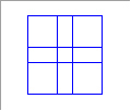
Tool Priority Preview |
The thumbnail in the lower right-hand corner of the Tool Assignment panel indicates the active tool priority.
|
|
| When
auto-assigning tools, the normal rule for AP100US is
to check the tool against the thickness of the sheet, in order
to select a tool that is strong enough for the metal.
The program will check sheet thickness and tool dimensions when auto-tooling if this box is in its unchecked (default) setting. Under these circumstances, only when the dimension of the tool is equal to or larger than the sheet thickness, will the single hit tool be successfully assigned to the pattern. When this box is checked ON, the program will NOT check the thickness of the sheet and will not compare it with the dimension of the tool when auto tooling. -- Be Careful! -- If this box is checked on and the program chooses a tool that is too small for punching on thick or hardened metal, it could potentially damage the tool.Note: The Disable Check Thickness for Single Hit feature will not take effect for C Radius, Rounded C or Special tools. |
||
The Tool Priority list updates according to the pattern type you select in the Pattern List. The Tool Priority indicates the selection order the system will use during Auto Tool assignments. The range of priority numbers is from 1 to 6, with 1 being the highest and 6 being the lowest. Some patterns have fewer than six priority values. For example, the Round pattern has a range of 1 to 4, while the Corner Notch pattern has a range from 1 to 6.
To change the priority order, select a pattern type in the Pattern List, and then select a tool assignment in the Tool Priority list. |
||
|
|
|
|
Click the Up Arrow button move the selected tool assignment upwards in the list, thereby assigning it a higher priority. |
|
|
Click the Down Arrow button to move the selected tool assignment downward in the list, thereby assigning it a lower priority. |
|
|
A Cancel icon next to a Tool Priority option indicates that it has a priority value of 0 (zero). The system will not use the option to assign tools. To remove the Cancel icon, double-click the option to display the priority number. Once the priority number appears, you can assign a priority value to the option. |
|