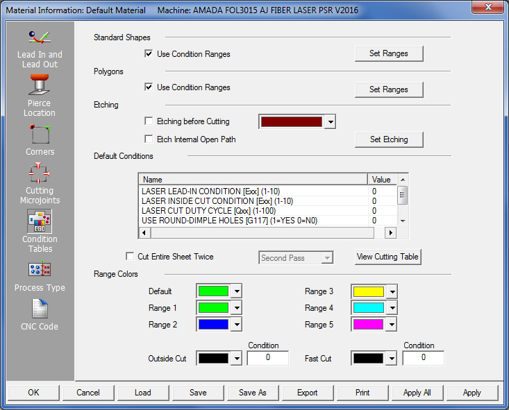
The Condition Tables panel contains options that allow the user to specify size ranges for the geometry and the condition nodes to apply to each range.
Condition Ranges are divided into three categories: Standard Shapes, Polygons and Etching. Standard Shapes processes the macro patterns that are selected in the Pierce Location panel. The Macro On option must be enabled for a Standard Shape in the Pierce Location folder before you can use the range options. If you remove the check mark from a standard shape Macro box, those patterns will use the Polygon ranges. See Pierce Location Properties.
To use condition ranges for Standard Shapes, Polygons or Etching, place a check mark in the respective Use Condition Ranges check boxes. If Use Condition Ranges are enabled, the software will compare the standard pattern sizes with the ranges and applies the correct conditions to the patterns. If you remove the check mark, the system cuts the standard shapes using the default conditions.
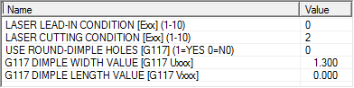
The Default Conditions section in the folder lists all the default values for the cutting conditions. The variables that are listed come from the machine driver. See Default Conditions.
Note: You do not need to specify all five ranges. The following example uses Range 1 through Range 5, but if 0.000 is in a Width To field, the range is eliminated.
The Set Ranges button in the Standard Shapes section allows you to specify the conditions to apply for the different sizes of macro shapes. When you click the Set Ranges button, the Range Settings window appears. The Current Range is indicated in the title bar, i.e., Current Range: 1. If you want to specify values for a range, click the desired range number in the Range # column.

You can specify five sets of condition ranges. The Range 1 though Range 5 conditions are color-coded. When you finish specifying the condition ranges and generate the sequence, the color codes are applied to the patterns. See Range Colors.
The range values that you specify are the Max Width (Maximum Width) values for each macro pattern. The following table outlines the type of width value the software uses to determine the range.
Macro Pattern |
Area Type |
Round Holes |
The diameter of the hole. |
Obround Slots |
The width of the slot. |
Rectangle Holes |
The width of the hole. |
Square Holes |
The overall size of the square. |
Radiused Rectangles |
The width of the hole. |
Single D and Double D |
The width value. |
Triangles |
The smaller side of the overall length and width. |
Radiused Slot |
The width of the slot. |
Range 1
The first range, Range 1, is from 0.000 to a value you type in the corresponding
Max Width field. In the above example, the value is 1.000.
This specifies that any macro pattern 1.000 or less will use the
conditions you select and define in the Conditions list for Range
1. You can select as many conditions as needed to modify any geometry
that falls within the range.
Range 2
The second range, Range 2, contains the second set of ranges. The second
range starts with the value typed into the Range 1 Max Width field
and appears in the Min Width (Minimum Width) field of Range 2.
You then specify the upper limit for the second range by typing a value
in the Max Width field of Range 2. In the example above, the value
is 2.000. This specifies that any macro pattern that is greater
than 1.000 and less than 2.000 will use the conditions
you select and define in the Conditions list for Range 2.
Ranges 3 - 5
Use the same procedure to specify any remaining condition ranges for the
standard shapes, progressively increasing each range size. If you try
to input a value that is less than the previous width, the software displays
an error message. Range 1 is the smallest set of values you can specify
for a particular range, while Range 5 is the highest. Range 5 is the greatest
value. If the width of a pattern exceeds the upper limit you specified
for Range 5, then the software uses the settings in the Default Conditions
list. (See Default Conditions.)
The Set Ranges button in the Polygons section allows you to specify conditions for non-standard shapes and part perimeters. The polygons and perimeters must form closed paths. The Current Range is indicated in the title bar: i.e., Current Range: 1. The window is divided into three panels, one for each pattern type: Polygon Conditions, Line Conditions and Arc Conditions. You can specify five ranges for polygons, lines and arcs, and define conditions for the entire path or for the individual lines and arcs.

Specify ranges for polygons using the same procedure described earlier for Standard Shapes. Whether the system will apply the conditions is dependent on the overall rectangular areas (zones) formed by the polygons. You type values in the Rect. Zone To (Maximum Area or Zone) fields and then select options and specify values in the Conditions list. Each range of values you specify must be greater than the previous range. If a zone or area exceeds the upper limit you specified for Range 5, then the software uses the settings in the Default Conditions list. See Default Conditions.
Select the Line Conditions tab and specify ranges for lines using the same procedure described earlier for Standard Shapes. Whether the system will apply the conditions is dependent on the overall lengths of the lines. Type values in the Max Length (Maximum Length) fields in the panel and then select options and specify values in the Conditions list. Each range of values specified must be greater than the previous range. If a length exceeds the upper limit you specified for Range 5, then the software uses the settings in the Default Conditions list. See Default Conditions.
Select the Arc Conditions tab to specify ranges for arcs using the same procedure described earlier for Standard Shapes. Whether the system will apply the conditions is dependent on the overall radii of the arcs. Enter values in the Max Arc Length (Maximum Arc Length) fields in the panel and then select options and specify values in the Conditions list. Each range of values specified must be greater than the previous range. If a radius exceeds the upper limit you specified for Range 5, then the software uses the settings in the Default Conditions list. See Default Conditions.
When the Polygon Conditions window opens, Use Same Condition for Entire Polygon is selected by default and the Polygon Conditions tab is active. The system examines the entire overall polygon size while range checking. The software examines the value in the Min Area field and uses the smallest size. See also: Use Line and Arc Ranges and Apply Line/Arc Conditions to Lead-In/Lead-Out.
To set conditions for individual lines and arcs, select Use Line and Arc Ranges, and then specify the values in the Line Conditions and Arc Conditions panels respectively. For lines, specify length values for the range checking. For arcs, specify the radius values for the range checking. If this option is selected, the software ignores the range checks for the polygons and instead uses the line and arc ranges.
Select Line/Arc Conditions Apply to Lead-In/Lead Out if to apply the current set of line and arc conditions to the lead-in and lead-out lines. If you place a check mark in the check box, and if Use Line and Arc Ranges is selected, the system will use the overall size or length of the lead-in or lead-out to determine whether to apply the range conditions you have specified for lines and arcs.
Etching Before Cutting
When this option
is checked, the software will sequence the Etched Patterns first, before
any of the regular cutouts. Etching, for Amada machines, uses
condition E10 and only scribes the material with lower power. After
all the Etching is complete, it will perform the standard cutting items.
Etch Internal Open Path
Check this box to allow the software to assign Laser tooling to an internal
Open Path. For certain types of internal non-closed loops (such as a single
line or some lines and arcs that do not connect to form a closed-loop)
the software can automatically assign Etching laser tooling, as opposed
to assigning regular laser tooling to them where the laser beam would
cut entirely through the part for such features.
The options in the Etching section allow you to specify the variables used for etching. Click the Set Etching button to open the Etching Conditions window to specify the conditions.
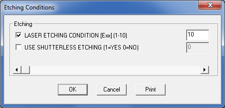

With the Etching Colors arrow button select a color for the etching condition from a standard color palette. Click the Other button to the right to define a custom color for the etching condition.
The system uses the values listed in the Default Conditions list when you do not specify a particular range, or when the standard shapes or polygons exceed the maximum range values.
Note: When the Use Condition Ranges options are enabled, or a default value other than 0 (zero) is specified, the range checks will always call the default if you manually change the cutting conditions. If you specify a value of 0 (zero) and disable Use Condition Ranges, the system will not set the default value.
Note: When Amada machines are loaded, different items display in the Default Conditions list. See Range Colors / For Amada Machine Users below.
Select Cut Entire Sheet Twice to cut the sheet twice. For example, you may want to cut the PCV coating before cutting the actual material. The option allows you to determine the conditions for each pass.
Enter range specifications manually as discussed below, or select a range from the Start Cut Attribute dialog, which will be used for both First and Second passes.
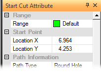
Access the Start Attribute dialog from Start/End Cut Attribute under the Sequence Features menu.
See Start and End Cut Attribute Options for more information.
Select First Pass from the Cut Entire Sheet Twice drop-down list to use the default conditions when processing the sheet during the first pass of the sequence.
Select Second Pass from the Cut Entire Sheet Twice drop-down list to use the range specifications for the remainder of the sequence. The second pass moves in the same direction as the first pass, the system now implements the condition checks and variables you specified for the standard shapes and polygons.
Click on the View Cutting Table button, to open a a five-tabbed cutting information table. The tabs are Cutting Process Info, Cutting Pierce Info, Cutting Edge Information, Nano Joint and Append tabs.
See View Cutting Condition Table for Cutting Condition info.
|
Specify a default system color or custom color for each range of sequenced geometry. The Default color is the same as the Pattern Sequenced color in the Color Preference folder of the Preferences window. You can assign the remaining five colors to the ranges. If you are not using a range, the default color is used. Note: For non-Amada machines the Outside Cut and Fast Cut options are disabled and default values in the Default Conditions list will be applied. |
For Amada Machine Users
When an Amada machine file is loaded, the Outside Cut Range Color pull-down with Condition field will display, and if an Amada AJ machine is loaded, the Fast Cut Range Color pull-down with Condition field will also display. These options allow the user to (1) assign a color to the Outside Cut (on a part perimeter) and manually add a condition, and (2) assign a color to the Fast Cut and manually add a condition.

When using Amada Machines, Default Condition Names appear as shown here
When Amada machines are loaded as described above, values entered in the Default Conditions list and values entered for Outside Cut Condition and Fast Cut Condition will work in conjunction. This means that the LASER INSIDE CUT CONDITION will only apply to inside cuts, the Outside Cut value will be applied to the outside perimeter and the Fast Cut value will be applied to Fast Cutting.
If Condition values for Outside Cut and/or Fast Cut are set to <0> then the LASER INSIDE CUT CONDITION will be applied to ALL cuts.
Note: Condition values entered for Outside Cut and Fast Cut are passed to the driver and appear as e-code in the NC file.
Function Buttons
Option |
Description |
OK / Cancel |
Click OK to keep any changes, or Cancel to close the window without saving.
|
Load |
Clicking the Load button displays the Open dialog box. If you want to change an existing tool inventory, use Open to load that tool inventory so you can make corrections. In addition to standard inv files, the user may choose to load from Tool Inventory files in .XLS or .CSV formats. From here it is also possible to create and edit .xls and .csv files. See Export below for more info on this.
|
Save |
To save changes made to material files, click the Save button. See Save for more info.
|
Save As
|
To save as an existing file that has been modified, click the Save As button. See Save As for more info.
|
| Export | Clicking Export opens the Save As window and allows the user to export files in .xls and .csv formats. See Exporting Files in XLS or CSV formats in the Material Files folder for more info on creating and editing .xls and .csv files.
|
To print the Material Type window with entries in the Material Type and Comments fields, click the Print button.
|
|
Apply All / Apply |
Click Apply All to apply all changes made in this window. Click Apply to apply only the most recent change. |