Option |
Description |
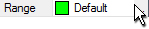
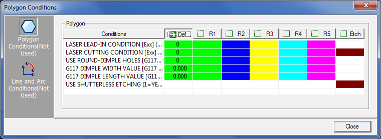
Range |
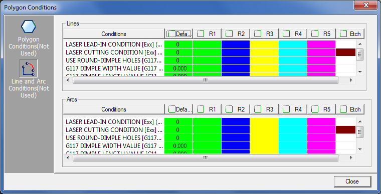
The Range option in the Range
section allows you to display the conditions assigned to the specific
patterns. Double-click the Range label or the navigation button
to open the Polygon Conditions window. |
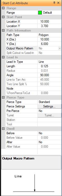
Range |
Start
Point |
If you want to modify the
actual coordinates for the start point, click either the Location
X or Location Y labels in the window to activate the New Location
buttons. Click the New Location button and move into the work
area. As you move the selected start point around the path, the
values in the Location X and Location Y fields update to indicate
the new coordinates. |
Location
X |
The X coordinate for the
start point. |
Location
Y |
The Y coordinate for the
start point. |
Path
Information |
The Path Information section
of the window displays the path type and size that you have selected
for editing. |
Path
Type |
This field displays the selected
path type, i.e., Round Hole, Rectangle Hole, etc. |
X
(Dia.) |
The X dimension or diameter
of the path. |
Y
(Dia.) |
The Y dimension or diameter
of the path. |
Output
Macro Pattern |
This option allows you to
change the macro status for the path. The status is either True
or False. If you select True from the drop-down list, software
will output macro code for the pattern. It also determines the
conditions and ranges to apply to the path. The range data is
extracted from the material file. |
Split
Cutout w/Lead-in |
Choose Yes to enable the
Split Cutouts option,
which lengthens existing lead-ins to split a cutout in half so
that it can drop safely between the workchute rollers. |
Lead
In |
The Lead In section of the
window allows you to view and edit the lead-in properties for
the start cut attribute. |
Lead
In Type |
You can change the Lead-In
type by selecting Line, Two Line, Line and Arc,
Hook, Cross Cut or None from the drop-down
list. Make sure to specify the appropriate values for the selected
lead-in using the Length, Radius, Angle and
Line to Tan (Tangent) Arc fields. |
Length |
Use this field to specify
the length of the lead-in line. |
Radius |
Use this field to specify
the arc radius of the lead-in line. |
Angle |
Use this field to specify
the angle of the lead-in line. |
Line
to Tan Arc |
Use this field to specify
the tangent arc value. |
Two
Line Split % |
Use this field to specify
the split percentage for the Two Line lead-in. |
Node |
Use the Node option to specify
a cutting condition. |
%
From Pierce To Cut |
Type a percentage value for
the cutting condition node. |
Pierce
Type |
The Pierce Type section of
the window allows you to specify the pierce type and pierce parameters
for the start cut attribute. |
Pierce
Type |
Select the desired pierce
type from the drop-down list: Standard, Shutterless, Power, Quick,
Peck, Power, Other or Pre-Punch. See
Pierce Type in Material Files. |
Pierce
Settings |
You can use this option to
view the current pierce settings for the start cut attribute. |
Pre-Pierce |
This option allows you to
change the pre-pierce status for the path. The status is either
True or False. If you select True from the drop-down list, the
system sequences a pre-pierce hole for the selected path. |
Turret |
If you select Pre-Punch as
your pierce type, you can use the Turret option to designate a
tool in the turret as a pre-punch tool. |
Station |
This field displays the station
number of the designated pre-punch tool in the turret. |
Tool |
This field displays the tool
type and size of the designated pre-punch tool in the turret. |
Dwell |
The options in the Dwell
section of the window allow you to specify a dwell before, after
or before and after the pierce. |
Before |
This option allows you to
change the dwell status before the system pierces the material.
The status is either Yes or No. If you select Yes from the drop-down
list, the system will insert a pause code before the actual pierce
command. |
Before
Value |
Use this field to specify
the actual dwell time in seconds. |
After |
This option allows you to
change the dwell status after the system pierces the material.
The status is either Yes or No. If you select Yes from the drop-down
list, the system will insert a pause code after the actual pierce
command. |
After
Value |
Use this field to specify
the actual dwell time in seconds. |
Node
Display |
This panel displays the currently
selected cutting conditions. |
Lead
In Type Display |
This panel provides a graphical
display of the currently selected lead-in type. |
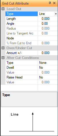
The End
Cut Attribute flyout window functions much like its counterpart,
the Start Cut Attribute window. It allows you to view and modify
the end point information for a path. You can modify the lead-out
properties, view the currently assigned condition range value,
specify overcut and undercut amounts and after cut conditions.
The options found in this window function like their counterparts
in the Lead In/Lead Out and Pierce Location folders of the Material
Information window. See Material Files. |
|
Option |
Description |
Lead
Out |
The Lead Out section of the
window allows you to view and edit the lead-out properties for
the end cut attribute. |
Type |
You can change the Lead-Out
type by selecting Line, Arc, Line and Arc,
or None from the drop-down list. Make sure to specify the
appropriate values for the selected lead-in using the Length,
Angle, Radius and Line to Tan (Tangent) Arc fields. |
Length |
Use this field to specify
the length of the lead-out line. |
Angle |
Use this field to specify
the angle of the lead-out line. |
Radius |
Use this field to specify
the radius of the arc. |
Line
to Tan Arc |
Use this field to specify
the tangent arc value. |
Node |
Use the Node option to specify
a cutting condition. |
%
From Cut to End |
Type a percentage value for
the cutting condition node. |
Over/Under
Cut |
The Over/Under Cut section
of the window allows you to specify the extent of the overcut
or undercut. |
Amount
+/- |
The default value is zero.
If the value is zero, the cut ends where it started. If you type
a positive value, the cut extends beyond the starting point. Conversely,
if you type a negative value, the cut stops short of the starting
point. |
After
Cut Conditions |
The options in the After
Cut Conditions section allow you to add code to the program after
each cut. |
Type |
There are three options on
the drop-down menu: None, Program Stop and Optional
Program Stop. Select None if you do not wan the system
to stop after each cut. Select Program Stop to output a
program stop. Select Optional Program Stop to output an
optional program stop. |
Dwell |
The Dwell option allows you
to specify a dwell after the cut. The status is either Yes or
No. If you select Yes from the drop-down menu, the system will
insert a pause after the cut. |
Dwell
Value |
Use this field to specify
the actual dwell time in seconds. |
Raise
Head |
The Raise Head option allows
you to raise the cutting head after the cut. The status is either
True or False. If you select True from the drop-down menu, the
system will raise the head to the preferred head-up height of
the machine unless you specify a raise head value in the field
below. |
Raise
Head Value |
Use this field to specify
the actual head-up height that you want to use after a cut. |
Option
Display |
This panel displays the currently
selected End Cut Attribute option in the window. |
Lead
Out Type Display |
This panel provides a graphical
display of the currently selected lead-out type. |