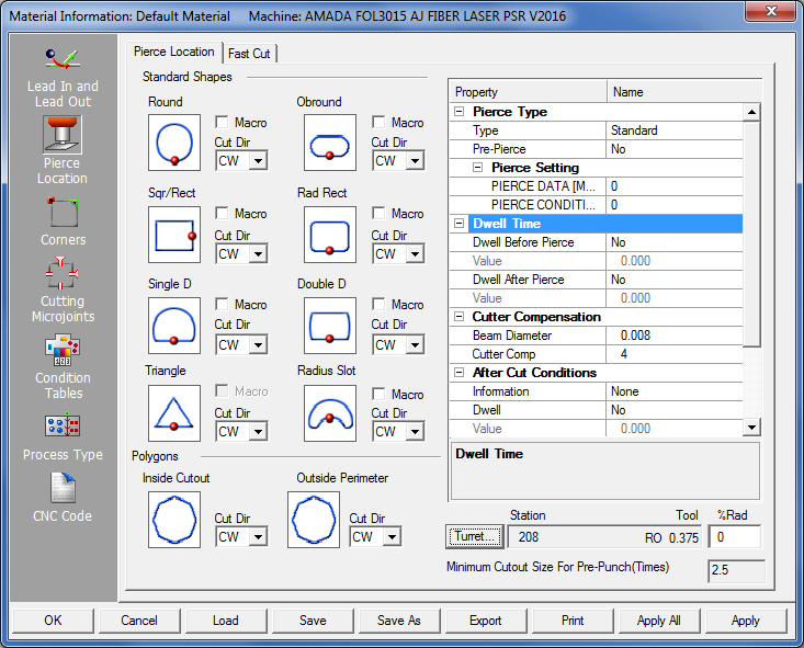
The Pierce Location panel contains options that allow the user to define the piercing for cutting and combination systems. Select the pierce type, the pierce locations on the geometry, and specify dwell times and cutter compensation.
Click for Fast Laser Cutting tab info.
Start Points indicate exactly where a path begins. Start points can be applied to standard patterns or to polygons. See Standard Shapes, Macro Code Generation and Polygons.
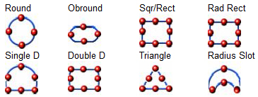
The Standard Shapes section contains all the shapes supported by the AP100US System: Round, Obround, Sqr/Rect (Square/Rectangle), Rad. Rect (Rounded Corner Hole/Rounded Corner Lines), Single D, Double D, Triangle and Radiused Slot.
There is also a Macro check box for each standard shape. If there is no check mark (the default setting), the software will not output macro code when cutting the standard shape. If you place a check mark in the Macro check box, the system will call the correct macro function in the machine driver when cutting the standard shape. The lead-in or lead-out type defined in the Lead In/Lead Out panel is replaced with a default lead-in line of the same length at the selected pierce location, 90-degrees relative to the cutting side of the pattern. The system also considers the shapes as one group when checking for ranges. (See Condition Tables.)
To specify the start point for a standard shape, move the pointer over the corresponding graphic and click the left mouse button to toggle through the available start point locations. The illustration below depicts the possible locations for each pattern. Continue to click the left mouse button until the start point moves to the correct location.
Note: Microjoints are not applied when the Macro option is enabled for a standard pattern. To apply a microjoint or tab to a standard pattern macro, you must specify a negative Under/Over Cut value in the Internal Geometry section of the Lead In/Lead Out folder. The tab or microjoint is formed using the undercut value when the lead-in or lead-out lines are cut.
Polygons are non-standard shapes consisting of lines and arcs. The illustration below depicts the possible start locations for polygons.
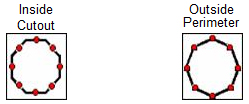
To specify the starting point for the Inside Cutout or Outside Perimeter, move the pointer over the corresponding polygon graphic and click the left mouse button to toggle through the available start point locations.
Note: If you do not want to apply a specific start point location for a polygon shape, click the Inside Cutout or Outside Perimeter graphic until the node appears at the last location, and then click once more to remove the node from the graphic display. If you completely remove the starting point from the polygon shape, the sequencing process determines the start point for the individual pattern.

Each standard shape or polygon pattern has a cutting direction associated with it. Specify the cutting direction as CW (clockwise) or CCW (counter-clockwise). Click the arrow button and select either CW or CCW to specify the cutting direction.
Notes: The cutting direction for the Polygons processes all the non-standard closed paths.
The Part Perimeter cutting direction processes the outside contour of the part.
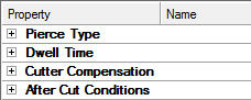
The Pierce
Location property table along the right side of the Pierce Location panel
contains the options for specifying the Pierce
Type, Pierce Settings,
Dwell
Time, Cutter Compensation
and After Cut Conditions.
Click the ![]() next to
an option to expand the hierarchical list and then select options from
the drop-down menus and specify values for the pierce parameters.
next to
an option to expand the hierarchical list and then select options from
the drop-down menus and specify values for the pierce parameters.
Right-click a blank area of the Pierce Location property table to open a shortcut menu that allows the user to Expand All Items or Collapse All Items.
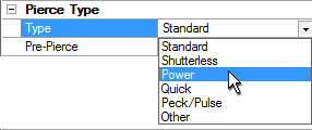
Select one of seven pierce options from the Type drop-down list in the Pierce Type section: Standard, Shutterless, Power, Quick, Peck/Pulse, Other, Pre-Pierce and Pre-Punch. Only one pierce type can be selected for the sequence. The pierce type for specific geometry can be edited only after the part has been auto-programmed.
When using a punching or combo machine, before selecting the Pre-Punch type, it is necessary to have a tool already designated as a pre-punch tool. See Sequence Features>Controlling a Pre-Punch Tool and Machine>Station Tool Information dialog for more info.
Option |
Description |
Type |
Select
the desired pierce type from the drop-down list. |
Standard |
The software outputs the
standard code for a pierce. |
Shutterless |
The
beam is activated and uses the parameters defined for cutting
without closing the shutter between cuts. Please note that the
trace line will appear bold (indicating head-down position) when
you select the Shutterless pierce type. The trace line will also
appear bold when both Trace On and Trace Head On are enabled in
the Cutting Options window.
Macro Patterns are disabled when Shutterless mode is used. |
Power |
The beam moves in a spiral
pattern to cut out the pierce hole before cutting the actual part
feature or pattern. Make sure to specify a radius value for the
pierce. |
Quick |
The
beam immediately starts the cut. |
Peck/Pulse |
The beam rapidly pulsates
and nibbles out the pierce hole. |
Other |
The
software outputs code indicating that some other pierce type is
used. |
Pre-Pierce |
IT may be preferable to pierce the entire sheet first and then have the system make the cuts. This reduces the amount of heat generated for thicker materials. When the piercing is complete, the system automatically returns to the pierce holes and begins cutting the patterns. The system sequences the sheet twice. The first portion of the sequence creates the pierce locations. The sequence order does not change; the system uses the same logic, but only pierces the sheet at the specified locations. The software then sequences the patterns, returns to the first pierce and starts cutting the geometry. This method allows for the heat generated in the area to dissipate. The system cuts the geometry in the same order of the pierce locations. The software displays a node pixel that is the same color at the pierce location. The software also places a Pattern Point at this location so you can easily edit the pierce position. |
|
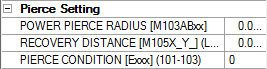
The options listed beneath Pierce Setting are dependent on the machine driver. The value specified for each option is passed to the driver, which in turn will output the code for the pierce.
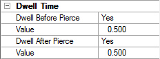
Specify a dwell for the pierce using the Dwell Before Pierce and Dwell After Pierce options in the Dwell Time section. Output a dwell either before a pierce, after a pierce or before and after a pierce. The two value fields allow the user to specify the actual dwell time.
The Beam Diameter and Cutter Comp fields in the Cutter Compensation section allow the user to specify the laser beam diameter and cutting compensation. Type in the actual diameter of the laser beam (or other cutting beam) in the Beam Diameter field, and a compensation value in the Cutter Comp field.
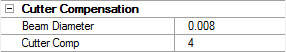
Note: The Beam Diameter input text box is dynamically linked to the same text box in the Process Type>Common Cutting section. Updating the value in one of these fields updates both accordingly.
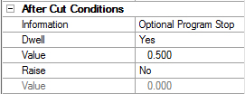
Use the options in the After Cut Conditions section to automatically add code to the program after each cut. There are four options: Information (Program Stop and Optional Program Stop), Dwell and Raise (Raise Head).
Pre-Punch
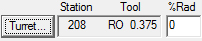
This option allows the user to select
the punch tool for a combination system. When you click the Turret button,
the Turret window appears. Select a station containing the punch tool,
click the Info button in the Station window and enable the Use for Pierce
Hole option in the Station Tool Information window. The station number,
tool name and tool size appear in the field next to the Turret button
after you make a selection and close the Turret window.
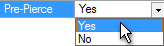
When you change the location of the Start Point of the Start Cut Attribute, if the Pre-Punch Tool interferes with other adjacent pattern, the system displays a warning dialog. Click Yes in the dialog to have the system will adjust the position of the pierce point automatically.
% Rad
This option allows you to control the
pre-punch tool percentage or radius from the pierce origin. The system
will step back the actual length of the lead-in to accommodate for the
percentage of the pre-punch tool radius
.
Note: You can also use Pre-Punch for a cutting system. The software passes
the variable status to the machine driver. You can process the sheet on
a punch press and then cut the remaining geometry on a laser system.
Minimum Cutout Size For Pre-Punch (Times)

This option allows the user to set a minimum size value that will be used for assigning the Pre-Punch tool. The user must enter a value that will be multiplied (Times) by the Pre-Punch tool Diameter, and that value will be used for assigning a pre-punch tool. Any pattern less than the value will not get pre-punched.
For example:
Pre-Punch Tool = .100 Dia
Minimum Cutout Size for Pre-Punch (Times) = 2.0
The system will take .100*2.0 = .200
This means that only patterns that are greater than .200 will get a pre-punch
tool.
Option Buttons
Option |
Description |
OK / Cancel |
Click OK to keep any changes, or Cancel to close the window without saving.
|
Load |
Clicking the Load
button displays the Open dialog box. If you want to change an
existing tool inventory, use Open to load that tool inventory
so you can make corrections.
|
Save |
To save changes made to material files, click the Save button. See Save for more info.
|
Save As |
To save as an existing file that has been modified, click the Save As button. See Save As for more info.
|
| Export | Clicking
Export opens the Save
As window and allows the user to export files in .xls and .csv
formats.
|
To print the Material Type window with entries in the Material Type and Comments fields, click the Print button.
|
|
Apply All / Apply |
Click Apply All to apply all changes made in this window. Click Apply to apply only the most recent change. |