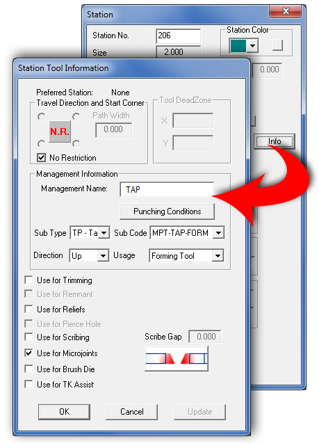
From the Station dialog, when the Info button for a station that contains a tool is clicked, the Station Tool Information dialog appears.
(See Creating and Editing Stations for more info such as how to open the Station dialog.)
Preferred
Stations
If preferred stations are listed for the selected tool in the tool inventory,
the stations are listed to the right of the label. The system only uses
this information if the current machine name matches the machine name
in the tool inventory.
Travel
Direction and Start Corner
Use the Travel Direction and Start Corner options to define the direction
Auto Sequence should use when sequencing this tool for code generation.
Click the Sequence Direction indicator graphic to toggle through the various
sequence direction options.
No Restriction
Check this box if you do not want to restrict the direction during sequencing.
Remove the check mark if you want to place restrictions on the sequence.
Removing the check mark will enable the four corner options.
Start Corner
Select one of the four Start Corner option buttons that surround the Sequence
Direction indicator graphic to determine where the sequencing begins.
Remove the check mark from the No Restriction check box to activate the
Starting Corner options.

Top Left. The sequencing for the tool will begin in the upper left corner of the sheet. The Line-By Line X option is chosen.

Top Right. The sequencing for the tool will begin in the upper right corner of the sheet. The Line-By Line X option is chosen.

Bottom Left. The sequencing for the tool will begin in the bottom left corner of the sheet. The Line-By Line X option is chosen.

Bottom Right. The sequencing for the tool will begin in the bottom right corner of the sheet. The Line-By Line X option is chosen.
For Management Information details, please see Tool Information Dialog.
Travel Direction
The Travel Direction toggle allows five choices -
![]() No Restriction. The system will sequence
the tool using the shortest distance from the last pattern sequenced.
No Restriction. The system will sequence
the tool using the shortest distance from the last pattern sequenced.
![]() Line-By Line X. Use this option to
sequence the tool along the primary X-axis, return to the original starting
edge, and then sequence the tool along the closest pattern off the primary
axis from the last sequenced pattern.
Line-By Line X. Use this option to
sequence the tool along the primary X-axis, return to the original starting
edge, and then sequence the tool along the closest pattern off the primary
axis from the last sequenced pattern.
![]() Line-By-Line Y. Use this option to
sequence the tool along the primary Y-axis, return to the original starting
edge, and then sequence the tool along the closest pattern off the primary
axis from the last sequenced pattern.
Line-By-Line Y. Use this option to
sequence the tool along the primary Y-axis, return to the original starting
edge, and then sequence the tool along the closest pattern off the primary
axis from the last sequenced pattern.
![]() X-Axis. Use this option to sequence
all patterns in the X direction before moving along the Y-axis.
X-Axis. Use this option to sequence
all patterns in the X direction before moving along the Y-axis.
![]() Y-Axis.
Use this option to sequence all patterns in the Y direction before
moving in the X direction.
Y-Axis.
Use this option to sequence all patterns in the Y direction before
moving in the X direction.
Tool Dead Zone Click for Tool Dead Zone information.
The “Use For” options allow the tool in the station to be designated for special uses. Multiple options may be checked for one tool.
Note: When a Special Tool is chosen, a Station Tool Information dialog with different options will display.
Use for Trimming
To use the tool in this station for trimming, place a check mark in the
Use For Trimming check box. The Trim Horizontal and Trim Vertical options
become available in the Punch Sequence menu.
When this option is checked, the tool will show the letter “T” in the Station # column in the Turret List window.
Use for Remnant
To use the tool in this station when punching remnants, place a check mark
in the Use For Remnant check box. This option can only be used for one
tool. If you previously selected a tool for punching remnants, the system
prompts you to override the previous tool. When this option is checked,
the tool will show the letter “R” in the Station # column in the Turret
List window. See
Sequence Remnant.
Use for Reliefs
This option appears in the Station Tool Information dialog if a round,
square or rectangle tool has been selected. Enabling this option allows
the system to use the tool as a relief tool. When this option is checked,
the tool will show the letter “L” in the Station # column in the Turret
List window. If a Special Tool is chosen, this option will not be available.
Use for Pierce Hole
This option appears in the Station Tool Information window if a round tool
has been selected. Enabling this option allows the system to use the round
for piercing. When this option is checked, the tool will show the letter
“P” in the Station # column in the Turret List window. If a Special Tool
is chosen, this option will not be available.
Note: This option is only enabled when a Combination machine is loaded.
Use for Scribing
This option appears in the Station Tool Information window if you want
to designate the selected tool in the station for use as a scribing tool.
Enabling this option allows the system to use the tool for scribing. When
checked the Scribe Gap field becomes active and values may be entered.
When this option is checked, the tool will show the letter “S” in the
Station # column in the Turret List window. If a Special Tool is chosen,
this option will not be available.
Use for Microjoints
Enabling this option allows the user to designate a selected tool in the
station for use as a microjoint tool. The system allows designating multiple
tools as a microjoint tools.
When a check is placed in the checkbox, and the user clicks OK in the Station Tool Information Dialog, the tool will show the letter “M” in the Station # column in the Turret List window.
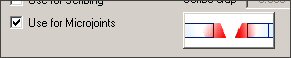
Placing a check in the
box displays the
Microjoint Placement toggle, as shown above
Toggle the Placement button to place the microjoint. A setting selected here will also show in the Material Files>Punching Microjoint Panel.
Use for Brush
Die
Check ON the option to allow a special tool to be used as a brush tool.
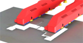
Brush
Dies are used between high forming dies to avoid or minimize scratches
to the parts by slightly elevating the material above the die surface.
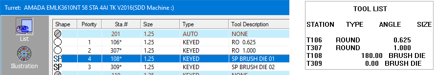
AP100US only allows using special tools as the place holder for a brush die. Double-click a row with a brush die to open the Station>Station Tool Info window.
Note:
The tool is not assigned to the part or sequence, it will automatically
output in the setup data for operator information only. This will only
apply if it's in the stations, not in the tool inventory.
Use for TK
Assist
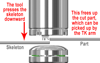
Processed parts may stick to the skeleton at a cut, making it difficult
for the TK pickup arm to lift the part out.
When this special tool is assigned to the edge of a part, all of the part perimeter (except for the last cut before TK engages) will be cut first and then the tool will hold the skeleton down while the part is being elevated and moved away from the skeleton. Then the last cut before the TK part pickup will take place.
To begin, a special TK Assist tool must be loaded into the Turret
Inventory>List view or ATC Storage and
then it must be activated for use as a TK Assist tool by checking ON the
Use for TK Assist option in the
Station Tool Info Window (shown at the top of this page). See Adding
Tools to the Turret for info on loading tools into the turret.
![]()
While in Part View, with the
part open in the work area and the Modules>Unloading
menu open, select Place TK Assist Tool
and then select a line on the boundary of part.
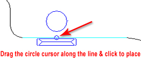
The large Round represents the body
of the tool that holds the skeleton down
The Assist Tool should be placed on any area that the operator thinks may have a "sticking" problem. Place as many tool hits as necessary. Delete tool assist hits by using the Delete option in the Draw / Edit menu tab.
Note: Used with Amada Combo machines only.Note: If the tool is used at different angles, it should be placed in an Auto Index station.
Punching Conditions
If the machine driver supports punching conditions for individual tools,
the Punching Conditions button is active. To view or modify the punching
conditions for a tool, click the Punching Conditions button. See Punching
Conditions Window.
Update
Click Update to renew the information for the tool in the currently selected
station. The information is updated from the tool data in the Tool Inventory.
This option is useful when using a tool inventory that was modified after
the current sheet or machine file was created. Click Update, and
the system updates the tool in this station only.
Note: This option may be disabled if NO changes have been made in the Tool Inventory.
OK / Cancel Click OK to save changes and return to the Station dialog or click Cancel to exit the Station Tool Information dialog without saving any changes.
When a Special Tool is chosen, this version of the Station Tool Information dialog box will appear. |
|
|
|
Tool Attribute |
|
Forming Height |
This is the Forming Height of the Special or Form Tool passed on from AP100Global or SheetWorks Data. |
Up / Down |
Select Up or Down to require the Forming direction to be formed Up or Down from the Material surface. (These options are enabled only if Forming Height was selected.) |
Marking (MK) |
Choose this option to assign a scribing or marking tool to the paths. |
Ext / Tap Height |
This is the extrusion or tapping tool height information passed on from AP100Global or SheetWorks Data. |
Up / Down |
Select Up or Down to require the Extrusion direction to be formed Up or Down from the Material surface. (These options are enabled only if Ext / Tap Height was selected.) |
OK |
Click OK to save your changes |
Cancel |
Click Cancel to cancel any changes and close the dialog. |