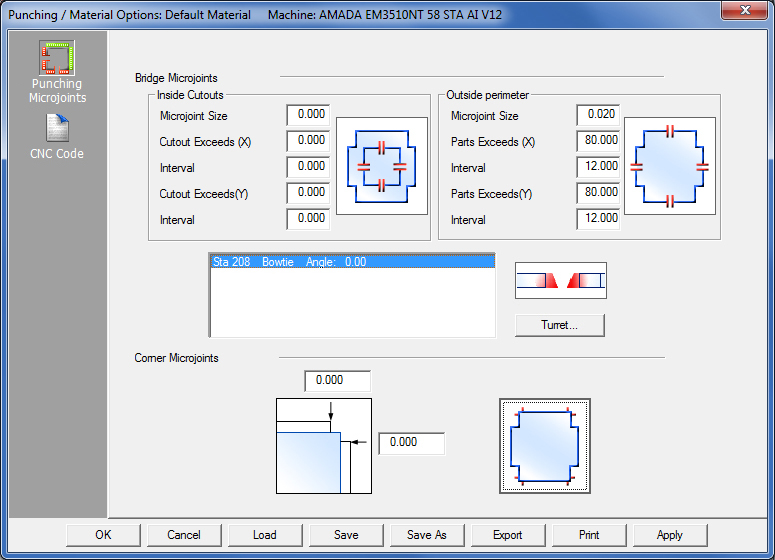
The options in the Punching Microjoints panel are for punching and combination systems. The panel is divided into Bridge Microjoints and Corner Microjoints sections. The options within these sections allow for the automatic placement of microjoints, bridge tools and tabs using shear tools while drawing or importing geometry.
Select Microjoint Tool First!
Before microjoints can be configured and applied, the user must first select
a tool as a microjoint tool (such as the Bowtie tool shown here).
For info on how this is accomplished, see How
to Select a Microjoint Tool.
This section allows the user to specify the default size of the microjoints, the quantity of the microjoints and the criteria for applying the microjoints at intervals according to the overall length and width of the part(s). These values can be applied to Inside Cutouts and the Outside perimeter.
Configure placement criteria for Inside Cutout microjoints based on part width and length.
Microjoint Size
Enter the value for the size of the microjoint. Microjoint size can vary according to material type and thickness, as well as the machine in use.
Cutout Exceeds (X)
Enter a value in the field. If the value entered is equal to or greater than the size of the cutout in X, the program will ignore the value in the Interval field and the user must place microjoints by clicking the Preferred Locations Toggle.
If the value entered is less than the size of the cutout in X, then the program will place microjoints according to the user-entered Interval value.
Interval
Enter a value for the Interval between microjoints in the field. The program will either use or ignore this field based on the value entered in Cutout Exceeds (X).
Cutout Exceeds (Y)
Enter a value in the field. If the value entered is equal to or greater than the size of the cutout in Y, the program will ignore the value in the Interval field and the user must place microjoints by clicking the Preferred Locations Toggle.
If the value entered is less than the size of the cutout in Y, then the program will place microjoints according to the user-entered Interval value.
Interval
Enter a value the Interval between microjoints in the field. The program will either use or ignore this field based on the value entered in Cutout Exceeds (Y).
Note: Cutout X and Y including Intervals do not need to be the same; different values may be assigned to these fields.
Configure the interval placement criteria for the Outside Perimeter microjoints according to the part width and length.
Microjoint Size
Enter the value for the size of the microjoint.
Part Exceeds (X)
Enter a value in the field. If the value entered is equal to or greater than the size of the part in X, the program will ignore the value in the Interval field and the user must place microjoints by clicking the Preferred Locations Toggle.
If the value entered is less than the size of the part in X, then the program will place microjoints according to the user-entered Interval value.
Interval
Enter a value the Interval between microjoints in the field. The program will either use or ignore this field based on the value entered in Part Exceeds (X).
Part Exceeds (Y)
Enter a value in the field. If the value entered is equal to or greater than the size of the part in Y, the program will ignore the value in the Interval field and the user must place microjoints by clicking the Preferred Locations Toggle.
If the value entered is less than the size of the part in Y, then the program will place microjoints according to the user-entered Interval value.
Interval
Enter a value the Interval between microjoints in the field. The program will either use or ignore this field based on the value entered in Part Exceeds (Y).
Note: Part X and Y including Intervals do not need to be the same; different values may be assigned to these fields.
Outside Perimeter Size and Interval Criteria
Microjoints applied to a 40 x 10 part with a microjoint size of 0.020 -
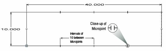
In the sample given above, the value in Part Exceeds (X) is less than the size of the part - Part size = 40.000, Part Exceeds (X) = 30.000.
In this case, the program will ignore the Preferred Locations Toggle and place microjoints on the part according to the user-entered value (10.000) in the Interval field. Notice in the diagram how microjoints in X are placed at intervals of 10.
The value in Part Exceeds (Y) is equal to the size of the part - Part size = 10.000, Part Exceeds (Y) = 10.000.
In this case, the program will ignore the value entered in the Interval field (2.500) and place single microjoints on both sides of the part according to the assignment selected in the Preferred Locations Toggle.
The Inside Cutouts section also functions in this way.
Note: The Preferred Locations Toggle can be seen as another way to assign microjoints. If the Cutout/Parts Exceeds in the X and/or Y are equal to or greater than the size of the part, then this toggle may be used.
Move
the cursor onto the graphic and left-click with the mouse to toggle through
the preferred locations for the microjoints.
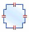
There are four possible settings:
|
|
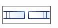
No microjoints. |
Four microjoints. The microjoints are assigned to all four sides of the part. The system will attempt to assign microjoints to the nearest most centered pattern on the furthest end, and the top and bottom perimeter boundaries. |
|
|
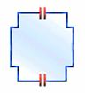
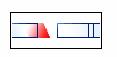
Two microjoints placed horizontally on the top and bottom perimeters of the part. |
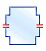
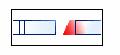
Two microjoints placed vertically on the left and right perimeters of the part. The system will attempt to assign a microjoint to the vertical edges of the perimeter at the center-most location on the right and left side of the part. |
This read-only field displays information for the tool (or tools) already chosen as the Microjoint tool.
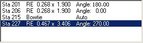
The various microjoint tools can have different angles, which will allow the system to auto-select a different microjoint tool if a part is rotated.
Highlight a station row and then click the Bridge Microjoint Placement toggle to assign a different placement to a microjoint tool (see below).
When Apply is clicked, microjoint tools are assigned to the part according to the following rules:
1. The microjoint tool has the same angle as the pattern;
2. If the tools are symmetrical, it can be assigned to symmetrical angles;
3. The microjoint tool that has the closest size to the tool on the pattern;
4. If more than one tool satisfies the requirements, the tool appearing higher in the Turret Tool list will be selected.
Note: This field is empty if no tools have been designated for use as microjoint tools.
See How to Select a Microjoint Tool for more info.
Placement for the Bridge Microjoint Tool
This option assigns a microjoint tool to the microjoint placements (described above). It is possible to NOT assign a microjoint tool at this point; a microjoint tool can be assigned at a later stage.
See Sequence Features>Punch Microjoint Options for more info.
|
Before/After Microjoint - Selecting this will place a Microjoint tool before and after the Microjoint. Note: A microjoint tool must be individually assigned to this placement. To
select a microjoint tool the user must choose the placement first,
click on the Turret
button, highlight the tool already selected as the microjoint
tool (or click Add to select a different tool) and click OK in
the Turret window. |
|
Before Microjoint - This option places the Microjoint tool before the Microjoint. Note:
The same microjoint tool must be assigned to both the Before and
After placements. |
|
After Microjoint - This option places the Microjoint tool after the Microjoint. Note:
The same microjoint tool must be assigned to both the Before and
After placements. |
|
No Microjoint - This option will not place any bridge microjoint tools. |
Notes: 1. When you select Before Microjoint or After Microjoint, the system will assign the tools according to the tool direction, not the start and end points of the patterns. 2. The system will always apply microjoints according to the width and length values specified for the interval criteria even if you do not set a preferred location. |
|
How to Select a Microjoint Tool
![]()
Click the Turret button to open the Turret List window. From there it is possible to select a microjoint tool.
Turret List window
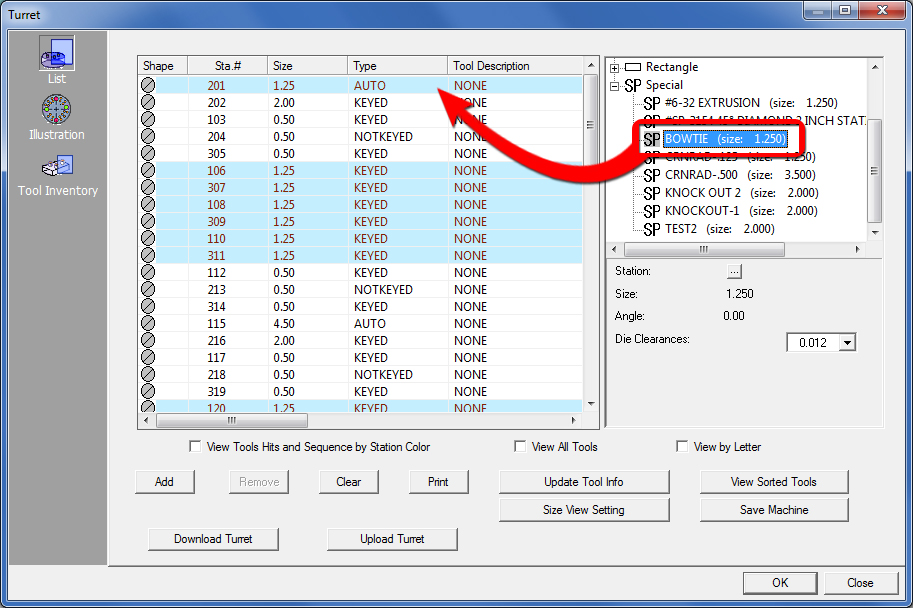
Drag the selected tool into the station on the left
Click the Add button to open the tool list that displays on the right side of the Turret List window. Be sure that View All Tools is checked in order to turn off any filters and display all tools in the inventory.
See Turret Window - Tool Inventory View for information about adding a tool inventory.
In the pane on the right, select a tool to be used as the microjoint tool. In the example above Bowtie is selected as it is commonly used as a microjoint tool. Drag the selected tool into the Turret List on the left. Stations that have the correct size and are suitable for the selected tool will be highlighted in blue. A microjoint tool may be placed in an AUTO station, which will allow the tool to rotate as needed.
When the preferred tool is in the Turret List, double-click that tool and the Station dialog box displays. Make changes to the values for the tool in this dialog if needed.
See Creating and Editing Stations for more information.
In the Station dialog, click the Info button and the Station Tool Information dialog box appears. In this dialog, select Use for Microjoints to designate the selected tool as the Microjoint tool. Click OK to save changes and close the dialog.Back in the Turret List window
When the Use for Microjoints is checked, the tool will show the letter “M” in the Station # column in the Turret List window as shown in this illustration.
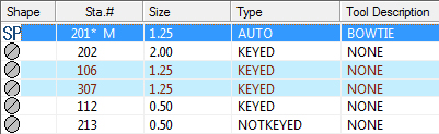
Station #201 will be used
for the Microjoint
tool, as indicated by the letter “M”
Click OK in the Turret List window to return to the Punching Microjoints window. Click Apply to apply the microjoints to the part(s), and then click OK to save any changes and exit the Punching Microjoints window.
See Adding Tools to the Turret for more details on the functions of the Turret List window.
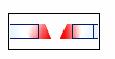
Corner Microjoints
The Corner Microjoints section of the Punching Microjoints panel allows the quantity of corner microjoints and the corner distances to be specified. Move the pointer onto the graphic and click the left mouse button to toggle through the microjoint assignments. There are three possible settings: No corner microjoints, four microjoints and corner microjoints applied to all adjacent 90-degree corners.
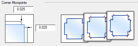
Note: The value fields become active when the second or third options are selected.
Option |
Description |
OK / Cancel |
Click OK to keep any changes, or Cancel to close the window without saving.
|
Load |
Clicking the Load button displays the Open dialog box. If you want to change an existing tool inventory, use Open to load that tool inventory so you can make corrections. In addition to standard inv files, the user may choose to load from Tool Inventory files in .XLS or .CSV formats. From here it is also possible to create and edit .xls and .csv files. See Export below for more info on this.
|
Save |
To save changes made to material files, click the Save button. See Save for more info.
|
Save As |
To save as an existing file that has been modified, click the Save As button. See Save As for more info.
|
| Export | Clicking Export opens the Save As window and allows the user to export files in .xls and .csv formats. See Exporting Files in XLS or CSV formats in the Material Files folder for more info on creating and editing .xls and .csv files.
|
To print the Material Type window with entries in the Material Type and Comments fields, click the Print button.
|
|
Apply All / Apply |
Click Apply All to apply all changes made in this window. Click Apply to apply only the most recent change.
|
Download / Upload Turret |
Download an SDDJ Turret Layout to the AP100US Turret File and tool inventory, or Upload an AP100US Turret file to the SDDJ database. Note: These options are available only for AP100US users, who are connected to an SDDJ Server. |