Fast Laser
Cutting
What
is Fast Laser Cutting?
Using Fast Cut is like choosing to drive
on a freeway rather than on surface streets. Streets have so many stops
that
a driver can never attain the speed limit, but on the freeway a driver
can achieve and maintain the highest speed possible.
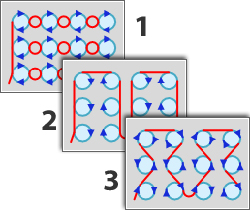
Usually
a laser head completely cuts out one pattern before moving on
to the next. But Fast Cut smoothly continues laser head motion
as though cutting out a figure 8. The laser head, moving in continuous
half-circles, cuts out the top of the first round (#1); the beam
then pauses while looping in a half-circle between patterns around
the lower half of the 8 (#2).
When
the laser head comes to the second round (#3), it powers up again,
cuts the top half, loops under #4 and continues in this way until
the upper half of all the rounds are cut (#5). Fast Cut then continues
around the last pattern to cut out the bottom halves (#5).
Entire
pattern groups can be cut in this manner, drastically reducing
overall laser cutting time. |
|
 |

Note: The option
is only available for AP100US Premium users. Ask your sales consultant
for more information.
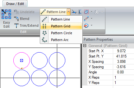
Create
a Pattern Grid
A good way
to begin is by dragging out a grid of similar patterns using options on
the Draw / Edit tab. The image here shows that one Round pattern was drawn
on a part and then the Round was gridded into a pattern using Pattern
Grid on the Draw / Edit menu. After the grid is placed the user
may then make adjustments in the Pattern
Properties pane. The user may first create a grid of patterns and
use Fast Cut directly on the grid, or if need be the grid may be Exploded,
because Fast Cut also works with patterns that are ungridded or ungrouped.
See Draw>Draw
Patterns and Edit>Edit Patterns
for more info. See also Cut
Sequence tab>Fast Cut on how to enable this feature from the AP100US
interface.
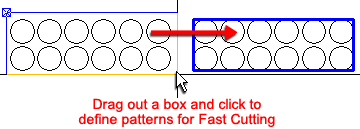
Define
Fast Cut
To define a
Fast Cut, the user must manually define a group of patterns by selecting
the Define Fast Cut option and then dragging out a box to enclose the
patterns to be Fast Cut. See the Cut
Sequence>Fast Cut options on the Cut
Sequence tab.
When this is done the system recognizes the pattern
shapes and applies the default Round pattern option set.
The user may
then select the specific type of Fast Cut by toggling through the option
buttons in the Fast
Cut Settings mini-window and choosing a different Round Hole option.
The program will then dynamically change the sequencing of the pattern.
Only patterns
that have been Fast Cut defined will be cut out using Fast Cut. All remaining
patterns will be bypassed, and the program will sequence these "undefined"
patterns according to default settings.
Different Pattern Sizes with Same Center
Point
Pattern groups may contain patterns of different sizes, but if they share
center-points that are in one line they can be defined and cut by Fast
Cut.
If
part sizes differ the program will default to inner-tangent
Fast Cutting regardless of the option selected by user
Notes:
Fast Cut focuses on smaller patterns that are nearer together. A grid of
larger patterns that are spaced farther apart may not be definable by
Fast Cut.
The Fast Cut
submenu will not display when a Combo machine is loaded.
Fast Cutting does not use lead-ins (except for the first pattern) or piercing.
Fast Cutting functions in both Part and Sheet views.
Amada
recommends these material specifications for Fast Cutting:
For 2kW & 3kW machines: Mild steel – Up to 1.6 mm. Stainless Steel
-1.0 mm. Aluminum -1.0 mm.
For 6kW or 9kW Amada FOL AJ or LCG AJ machines materials up to 12 gauge
can be Fast Cut.
Selecting
Fast Cut Options
Options chosen
will give results that can differ according to many different variables,
such as operator experience and machine characteristics when cutting a
certain arrangement of patterns/parts on a sheet. This section is intended
to serve as general guidelines.
The user may
view instructive Demo Videos for the
Fast Cut feature, in addition to other New Enhancements in this release.
 |
|
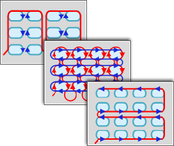
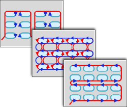
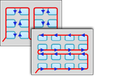
Round Hole Fast Cut Options
Sequence
1: Round hole with Arc tangent. Use with Amada's FOL Laser Machine.
Sequence
2: Round hole with Line tangent. Use with Amada's FOL Laser Machine.
Sequence
3: Arc and Line tangent. Use with Amada's LCG Laser Machine. Use
this option in conjunction with Area Fast Cut when ungridded (exploded)
Round patterns of different sizes are on a part.
Note:
The red lines indicate laser head movement between patterns when
the laser is powered OFF. The laser head retains the same distance
from the part throughout the process. The laser head will loop
between patterns wherever the distance between patterns is less
(noticeable especially in Sequence 1).
|
|
|
Double D Fast Cut Options
Sequence
1: Line tangent. Use with Amada's FOL Laser Machine.
Sequence
2: Arc and Line tangent. Use with Amada's FOL Laser Machine.
Sequence
3: Line tangent. Use with Amada's LCG Laser Machine.
|
|
|
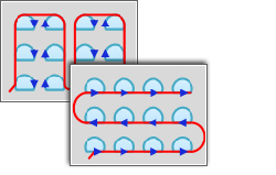
Obround Fast Cut Options
Sequence
1: Obround with Line tangent. Use with Amada's FOL Laser
Machine.
Sequence 2:
Obround with Arc tangent. Use with Amada's FOL Laser Machine.
Sequence 3:
Obround with Line tangent. Use with Amada's LCG Laser Machine.
|

|
|
SQ/RE Hole Fast Cut Options
Sequence 1:
Square with Line tangent. Use with Amada's FOL Laser Machine.
Sequence 2:
Square with Arc tangent. Use with Amada's FOL Laser Machine. With
this option Arc Radius and Distance values may be entered to avoid
conflicts with adjacent patterns.
Red line indicates
laser head movement
Sequence
3: Square with Line tangent. Use with Amada's LCG Laser Machine. |
|
|
Rounded Corner Hole Fast Cut Options
Sequence
1: Single D. Use with Amada's FOL Laser Machine.
Sequence
2: Rounded Corner Hole. Use with Amada's LCG Laser Machine.
|
 |
|
Single D Fast Cut Options
Sequence
1: Single D. Use with Amada's FOL Laser Machine.
Sequence 2:
Rounded Corner Hole. Use with Amada's LCG Laser Machine.
|
|
|
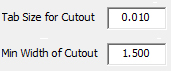
Use these
options to place a [microjoint] tab on cutout corners to prevent
loose cutouts from tilting and causing a collision or other stoppage.
Enter
a size for the tab on a cutout. A default of 0.010 is given, but
the user may adjust this as needed.
Enter
the minimum width of cutouts to be tabbed. If the cutout is smaller
than 1.5 (default), there is no need for a tab because a small
cutout should drop harmlessly from the table. User may adjust
this value as needed.
|

|
|
Click
Advanced
Settings to open the window shown here - |
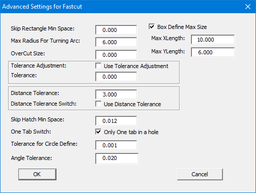
Values entered here are passed to the C:\AP100US\Parm\FastCutSet.ini
file
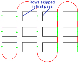
Skip
Rectangle Minimum Space
Using Fast Cut when distances between patterns are very close causes the
head to slow down between rows and also creates a lot of heat on the part
(for example, when etching bar codes on parts). To counteract these problems,
the user can enter a value in the Skip
Rectangle Minimum Space field to enable the “skip” option.
Distances in
X/Y between patterns that are equal to or smaller than the value entered
will be skipped by the program. When Fast Cut finishes the first pass,
it will return again to cut the skipped rows, but in reverse order. This
allows a steady laser head movement to be maintained, while allowing rows
to cool off after being cut.
Skip Fast Cutting in the Y direction
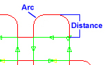
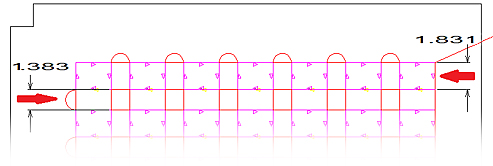
Max
Radius for Turning Arc
When Fast Cut turns to the next pattern using a tangent arc, if the turning
arc is too large laser head movement may exceed the table size. If the
arc is larger than the value given, the system will use a direct line
cut to go to the next point.
For example,
if a value of 1.5 is entered we can see that the distance between lines
on the left is 1.383, smaller than the value entered. This means that
Fast Cut will use an arc. But because the distance on the right is larger
than 1.5, Fast Cut will turn the arc using straight lines.
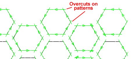
OverCut
Size
The purpose of this option is to make sure that a cutout has been fully
cut and will easily drop from the sheet. The option will make an oversized
(longer) cut, based on the value set in the OverCut Size field.
Box Define Max Size
Define the maximum length
of a Defining box in X and Y. The user must enable the option in the C:\AP100US\Parm
folder by placing a "1" as indicated.
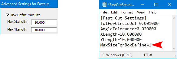
Note:
Based on the Max values entered for Fast Cut boxes, the system will coordinate
and even out the size of each box for a neater sheet.
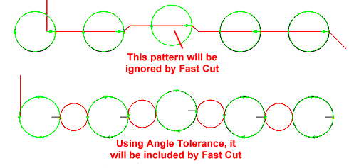
Tolerance
When Fast Cut is cutting a group of patterns,
if one line is a little “off” (maybe longer or shorter) it will be ignored
by Fast Cut. After the patterns have been cut, the system will then have
to send the laser head back to make that one cut. There are two methods
to resolve this -
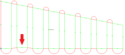
Tolerance
Adjustment - Use Tolerance Adjustment
If the user checks ON the Use Tolerance Adjustment switch and also enters
a value in the Tolerance field, if the lines are within the given tolerance,
the pattern will be adjusted in the X or Y direction to make sure it is
in the same line along with the other patterns.
Fast Cut straightened out (moved) the
uneven line and made an even cut
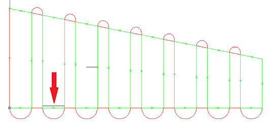
Tolerance
Tolerance allows Fast Cut to adjust the cutting line, to include an uneven
line in the fast cut as in this image. To enable enter a tolerance value
in the Tolerance field. The Use Tolerance Adjustment checkbox should be
switched OFF for this option.
Notice that the uneven line indicated by the
red arrow was included in the Fast Cut
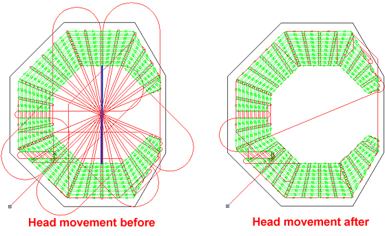
Distance
Tolerance
If the distance
of the trace line for Fast Cut is very large, the head movement may take
up too much time when fast cutting. In order to resolve this problem,
add a distance tolerance value. If the distance between patterns is greater
than the given Distance Tolerance value, then Fast Cut will not be enabled.
In the image on the left the system is trying to Fast Cut the entire array
of patterns; notice the amount of head movement. The image on the right
shows how much head movement was decreased after enabling this option.
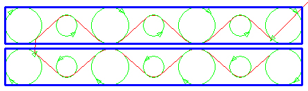
Distance
Tolerance
A large Distance Tolerance value allows Fast Cut to cut an array of patterns
as one cut, but the head movement may take up too much time. Entering
a smaller value allows Fast Cut to divide the pattern array into several
manageable sections, thereby controlling head movement.
Distance
Tolerance Switch
To enable Distance Tolerance, check ON the Use Distance Tolerance checkbox.
Skip
Hatch Minimum Space
This option allows Hatch Etching and Fast Cut properties to be used together.
If the value in Skip Hatch Min Space is larger than the Hatch Interval
value set in Hatch Etching, Fast Cut will
skip the next hatch etch line and cut the line after that one instead.
Since the distance
between patterns when using the Hatch Etching
option is also very close, the skip method can make the cutting speed
faster and is good for heat dissipation. If the value in “Skip Hatch Min
Space” is larger than the Hatch Interval value set in Hatch Settings,
Fast Cut will skip the next hatch line and cut the line after that one
instead (similar to Skip Rectangle Min Space above).
One
Tab Switch
If this option is checked ON, Fast Cut will leave only one tab in a cutout.
With the option checked OFF, the program may add several tabs in one cutout.
This option works in conjunction with the Tab Size for Cutout and Min
Width of Cutout value fields shown above.
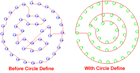
Tolerance
for Circle Define
When defining a pattern circle, Fast Cut will attempt to place patterns
in a group. To do this, a circle center point or points between patterns
must be identified by the program. Entering a tolerance value means that
Fast Cut will assign a common center point to multiple center points that
are within a certain distance from each other (within the tolerance value).
Center points outside of that distance will be recognized by the system
as separate center points.
Note: Using
a large tolerance value allows the program to regard multiple center points
as one center point. In such cases Fast Cut can only guarantee the accuracy
of the cut on the first pattern - cuts on following patterns may become
increasingly inaccurate (off center).
Angle
Tolerance
Fast Cut will calculate the spacing between patterns. If one pattern is
off center, Fast Cutting will be interrupted. For example, when trying
to define a circle line, Fast Cut will notice that one circle is not directly
in line with the others. To counter this the user may then enter an Angle
Tolerance value, enabling Fast Cut to define all the circles as one line.