Users may customize the Ribbon Interface by changing icon style and placement.
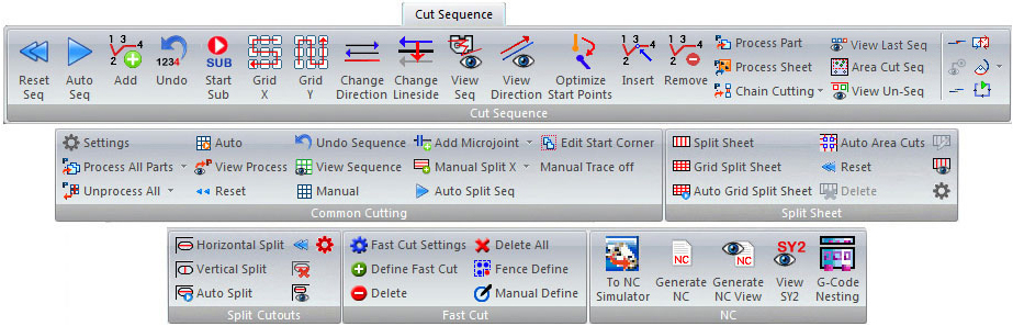
Cut Sequence Ribbon tab
Users may customize the Ribbon Interface by changing icon style and placement.
|
|
|
|
Reset clears any previously defined sequence.
Click for more Reset Cut Sequence info.
|
|
The Auto Sequence option instructs the system to determine the sequence.
Click for more Auto Cut Sequence info.
|
|
The Add option allows you to manually sequence cutting patterns in any order.
Click for more Add Cut Sequence info.
|
|
This option allows you to eliminate the last pattern (or function) added to the sequence without resetting the entire sequence.
Click for more Undo Last Cut Sequence info.
|
|
These options allow you to start a subroutine, select a group of patterns on a part and then sequence that group of patterns across the entire grid.
Click for more Cutting Subroutines info.
|
|
Once you start a subroutine and choose the patterns on the first part, use Grid X to close the group and duplicate the sequence in the horizontal (X) direction.
Click for more Grid X info.
|
|
Once you start subroutine and choose the patterns on the first part, use Grid Y to close the group and duplicate the sequence in the vertical (Y) direction.
Click for more Grid Y info.
|
|
If you need to change the cutting direction, select Change Direction from the Pattern Attributes submenu and move into the work area.
Click for more Change Direction info.
|
|
If you notice that a pattern cuts on the wrong side of the path, select Change Side and move into the work area.
Click for more Change Side info.
|
|
If you want to see the sequence, select View Sequence. The sequence displays as the work area redraws.
To allow the program to show the part unloading process as soon as the sheet is sequenced while in the Cut Sequence menu, make sure that the Auto Unloader checkbox in Machine Setting>Sequence Info is checked ON.
Click for more View Cut Sequence info.
|
|
If you have disabled Show Cutting Direction in the Display Options panel of the Preferences window, but want to refresh the display and view the cutting direction, select View Direction.
Click for more View Cutting Direction info.
|
|
Selecting this function changes the location of the start points on the part/sheet to optimize machine head travel.
Click for more Optimize Start Point info.
|
|
The Insert option allows you to add patterns that were omitted from the cut sequence. Click for more Insert Cut Sequence info.
|
|
The Remove option allows you to eliminate patterns from the sequence. Click for more Remove Cut Sequence info. |
|
To process one part, select Process Part.
Click for more Process Part info.
|
|
To process the patterns on the entire sheet, you must first activate Sheet view.
Click for more Process Sheet info.
|
|
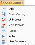
Options on the Chain / Bridge Cutting flyout menu allows you to use one continuous cut to process all the part profiles.
Click for more Chain and Bridge Cutting info. |
|
To view the last sequenced cutting path, select View Last Sequenced.
Click for more View Last Sequenced info.
|
|
The Area Cut Sequence button allows the user to add a sequence to an area. To do so, click the icon and then drag out a rectangle in the work area on the sheet; all the patterns inside the rectangle will be added to the sequence.
Note:
If the rectangle width is less then the height, then the system
will use X path width sequence. If the rectangle width is greater
than the height, then the Y path width is used.
|
|
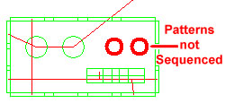
To view unsequenced patterns on a part or sheet, click the View Unsequenced Patterns icon. The pattern(s) that are unsequenced will be hi-lited in red.
When using a combo machine, a pattern will remain unsequenced if a suitable tool could not be found for it when it was tooled in the Tool Assignment tab. Also, Try adjusting settings for Nibble Pitch and/or Die Clearance settings that may be blocking tool assignment for a pattern.
See Preferences>Tool Assignment and Tool Settings for more info on Nibble Pitch and Die Clearances. Nibble Pitch and Die Clearances can easily be toggled ON/OFF on the Toggle Toolbar in the lower right-hand corner of the AP100US program.
|
Other Options |
|
|
Manually Join Paths allows you to choose which end points the system should consider as joined so you can group the patterns to create one path.
However, if you need to separate grouped patterns to create individual paths, use Manually Split Paths.
Click for more Manually Join Paths or Manually Split Paths info.
|
|
If you need to view the sequence of the pre-punch tool assignments, select Toggle Pre-Punch.
Click for more Toggle Pre-Punch info.
|
|
You can use Partial Cut Segment to apply segmented cutting along a line or arc.
Click for more Partial Cut Segment info.
|
|
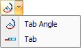
Options on the Tabs and Tab Angles flyout menu are used for extending or shortening the cutting path.
Click for more Tabs and Tab Angles info.
|
|
This option allows the user to add an extra cut to a cut sequence, in order to cut out a slug that may hinder the part remover. This option becomes active after the part/sheet has been sequenced. Click the Notch Cut Out option and the program will resequence and add cutouts where needed.
See Perimeter Notch Relief>Notch Cut Out for info on other Perimeter Notch Cut Out options.
|
|
The Common Cutting module calculates the most efficient cutting of a sheet when parts share a common boundary.
AP100US is able to cut internal patterns and common cuts together part by part if desired. Microjoints between parts can then be applied to reduce the chances of material deformation during cutting.
See Common Cutting Module for more info. Note: To engage this option Macros must be turned off.
Note: Common Cutting (part-by-part, row-by-row and straight common cutting) between different common cutting groups is supported.
|
|
|
Click to open the Common Cutting Settings dialog, which contains the various settings needed when using Common Cutting . |
|
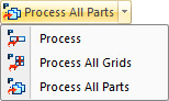
Click the drop-down arrow to display the Process All Parts flyout menu with process parts options. Use these options to prepare the parts on the sheet for common cutting.
See Processing Options for more info. |
|
Click the drop-down arrow to display the Unprocess flyout menu with unprocessing options. Use these options to reverse the processing individual parts.
See Processing Options for more info. |
|
Select Auto from the Common Cutting submenu to automatically sequence all parts on the sheet that were processed for common cutting.
|
|
Use the View Process option to view the process and determine which parts have been processed for common cutting.
|
|
Select Reset to clear the common cut sequence. Using this option does not affect processing on a grid or parts.
|
|
Use the Undo Sequence option to unsequence the last common cutting group sequenced.
|
|
To see the common cutting sequence, select View Sequence.
|
|
To sequence individual common cutting groups, select Manual. Sequencing must be added to both the inner hole and common cut when using this feature in the Common Cutting tab.
|
|
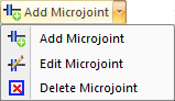
Add a Microjoint between parts by clicking this option and then moving the crosshair cursor into the work area. Click on any snap point and the cursor will change to a small circle which will follow the outer perimeter of parts. Move the circle-cursor to the place between parts where the microjoint is to be placed and left-click to finalize.
Click Edit a Microjoint Select this option and then cursor into the work area. When the cursor gets near a microjoint it will snap to it and change into a small blue square. Left-click to open the Microjoint panel and make any necessary changes. Hit <Enter> to finalize changes or hit <Tab> to move to the next field.
Select Delete Microjoint and then cursor into the work area. When the cursor gets near a microjoint it will snap to it and change into a small blue square. When the square-cursor hovers over a microjoint, left-click to delete.
|
|
Using the Manual Split X or Y option, the user can add segments of Splits from the Common Straight Edge Cut to the part or sheet edge, or to the other Common Straight Edge Cut, which can be controlled as independent line patterns on the sheet for sequencing in the X or Y. (Compare this to the Split Sheet function, where splits are sequenced dynamically based on the relationship of the parts.)
Manual splits can also be added between parts. See Sequencing Options in Common Cutting for more info.
|
|
Click to auto-place splits on the sheet between parts. See Sequencing Options for more info.
This button is only active after parts have been processed.
|
|
This
option allows the user to select the Common Cutting Start corner
for single or multiple straight edge cutting. The parts/grid must
first be processed using the Process option in the Common Cutting
sub-menu (see above) and Straight
Edge Cut in the
Common
Cutting Settings dialog
must be selected.
Click the icon and move the crosshair into the work area. Left-click on or near the desired corner of the grid. Click on Edit Start Corner for more info. |
|
Enabling
Manual Trace off to allow the laser head to ignore holes in the
sheet from corner notch cutouts and continue normal laser head
movement, thus avoiding a possible collision.
By default Manual Trace is ON. Select the option to turn Manual Trace OFF and then click on part corners that have notches. Process Parts/Grids first to enable the option (see above) and check ON Straight Edge Cut in Common Cutting Settings. See Manual Trace off for more info. |
The Split Sheet options allows the user to auto-cut a sheet into smaller sections in the X and Y directions for easier handling while unloading.
Click for more Split Sheet info.
|
|
|
Use this option to apply individual "split" cuts to a sheet when in Sheet View.
Notes: When placing vertical or horizontal cuts by clicking on an open area or part, the system automatically makes the necessary calculations and decides whether a line in the X or the Y is most applicable. This is based on user-entered values in the Split Sheet Settings dialog, the and internal calculations made by the software as it considers sheet size, amount, size and arrangement of parts, etc.
The system will automatically calculate and under cut for clamp dead zones.
See a sample of a sheet with Split Sheet cuts in place.
|
|
This will auto-grid the sheet based on number/arrangement of parts and where the user clicks when placing the split cut and user settings.
|
|
When this button is selected, the sheet is immediately gridded according to the number/arrangement of parts and user settings.
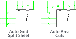
With this option, horizontal and vertical cuts will overlap, cutting the sheet into even smaller pieces. (See the results comparison between Auto Grid and Auto Area Cuts in the image below.)
|
|
When this button is selected, the sheet is immediately gridded according to the number/arrangement of parts and user settings.
With this option, horizontal and vertical cuts do not overlap.
Image of the same part near the corner of a sheet using Auto Grid and Auto Area options
|
|
After "split" lines have been placed, click Reset and then hit <y> on the keyboard to remove all "split" lines from the sheet. Hit <n> to cancel the operation.
|
|
After "split" lines have been placed, to individually remove unwanted lines select Delete and then move the cursor into the work area. Click on individual "split" lines to delete.
|
|
Edit allows the user to select and move individual cut lines.
|
|
View allows the user to see the sequence of the split sheet cuts. This does not include the sequence of the parts.
|
|
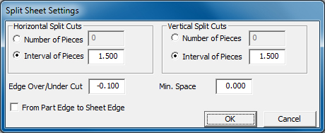
Select to open the Split Sheet Settings dialog, which is a scaled-down version of the Split Sheet options found in the Material Info>Process Type>Split Sheet tab. Values and Options selected here will also be updated in the Split Sheet tab.
For Horizontal and Vertical cuts select to cut the sheet into a specific number of pieces, or the size of the interval between cuts.
Edge Over/Under Cut allows the user to over-cut (Edge Over) or under-cut the edge of the sheet. A negative value of -0.100 allows the cut to extend one hundredth of an inch over the edge of the sheet. A value of 0.00 will cut to the very edge.
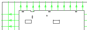
Select From Part Edge to Sheet Edge to cause the cut to begin at the part and run outward toward the edge of the sheet as shown in this image -
Min. Space is the value that the distance or interval between cuts cannot be less than.
The remaining option found only in the main Split Sheet tab allows the user to begin the split sheet sequence before or after the parts on the sheet are sequenced. The default setting causes the split sheet sequence to occur before, which is preferable in most cases.
|
Note: The Split Cutouts submenu is switched OFF by default and does not display. The user must switch ON the option by changing a setting in the Parm folder. See Split Cutouts for more info on enabling, configuring and using the option.
|
|
|
Like the Split Sheet function, Split Cutouts allows the user to cut internal slugs into smaller sections in the X/Y directions to allow them to fall through the slats of the shuttle table. There's no need to reset the cutting sequence, because the system will automatically include a split in the existing sequence.
Click Horizontal or Vertical Split to place a split in a hole by left-clicking. This feature automatically calculates the size of the hole.
|
|
Selecting this option allows the program to select holes that should be split.
Note: The splits placed by the program are visible only when the part is sequenced.
|
|
After "split" lines have been placed, click Reset and then hit <y> on the keyboard to remove all "split" lines from the holes. Hit <n> to cancel the operation.
|
|
After "split" lines have been placed, to individually remove unwanted lines select Delete, then move the cursor onto the part and click on individual "split" lines to delete.
|
|
Click to view the sequencing of the splits.
|
|
Click
this icon to open the Auto Split Settings for the Auto Split option.
|
|
|
|
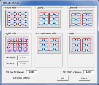
Click to display the Fast Cut Settings mini-window showing Fast Cut pattern cutting options. When the user defines a pattern grid other options may then be selected.
This
mini-window is synchronized with the
Notes: Fast Cut works with gridded or ungridded patterns. See Draw>Draw Patterns and Edit>Edit Patterns for more info on creating pattern grids.
See Material Files>Pierce Location Panel>Fast Laser Cutting for complete info.
Note: Options such as Start and End Cut Attributes are disabled for patterns that are defined for Fast Cutting.
|
|
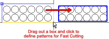
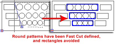
To define a Fast Cut, the user must manually define a group of patterns by selecting the Define Fast Cut option and then dragging out a box to enclose the patterns to be fast cut.
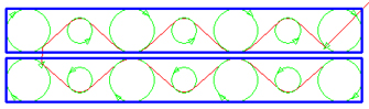
The user may then select the specific type of Fast Cut by toggling through the option buttons
in the Fast Cut Settings
mini-window (shown above) and choosing a different Round Hole
option. The program will then dynamically change the sequencing
of the pattern. Only patterns that have been Fast Cut defined will
be cut out using Fast Cut. All remaining patterns will be bypassed,
and the program will sequence these "undefined" patterns
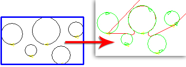
according to default settings. Different
Pattern Sizes with Same Center Point
|
|
To remove Fast Cut selections, click Delete and then click on the Area Fast Cut box in the work area. After deleting it may be necessary to refresh the work area by rolling the center mouse button.
Click Delete All to delete all Fast Cut selections anywhere on a part. |
|
Fence Define allows users to select odd-shaped pattern groups, while avoiding selecting adjacent patterns. Left-click to place the various points for the fence frame, right-click to join the lines and left-click again to finalize the Fence Define boundaries.
|
|
To apply Fast Cutting to individual Round patterns that are of different sizes and may not be placed in evenly arranged rows, select Manual Define. Click the Manual Define icon and then select the Rounds in the order that they are to be cut in.
After Rounds have been selected, terminate the Manual Define operation by right-clicking or pulling the cursor completely out of the work area. Select Manual Define again and begin left-clicking to define other Rounds on the same part. The system automatically chooses the most suitable tangent to make the Fast Cut.
Note: Manual Define will not work on Round patterns that are gridded or grouped. For Rounds that have been gridded, use the Edit>Explode option to create individual Rounds, select Manual Define and left-click each Round individually. |
|
|
|
If you have installed FabriSIM on your system, you can view a simulation before actually transmitting the NC code to your machine.
Click for more Send to NC Simulator info.
|
|
|
|
Click Generate NC to generate the code, or Generate NC View to generate the code and view it in the NC Sequence Viewer. Such files are saved in the NCFiles folder in the AP100US installed folder and can be viewed later in WordPad or Notepad.
Note: This step is usually taken after the sheet is finalized, sequenced and the part unloading sequence has been completed. Also, generating the NC file automatically generates the SY2 file required by the Automation Simulator.
Click for more Generate NC and Generate NC View info.
Note: When saving files, Part Name should be less than 32 characters. If the name exceeds this limitation, AP100US will automatically shorten the name.
|
|
SY2 code allows the user to view positional data for part remover arms. It is auto-generated when the user clicks on Generate NC or Generate NC View and saved in the NCFiles folder in the AP100US installation folder. (Note: Auto Unload in the Modules menu must first be run before this step can be taken).
When this option is clicked, the file opens in WordPad; saved SY2 files can also be opened later in Notepad.
Note: This driver-dependent option appears only when using newer Amada machines.
|
|
Select to create a GTM or LMT file for G-Code Nesting.
Click for more G-Code Nesting Integration info.
Note: The coordinate option is used to assist the user by showing cursor coordinates in the work area. |