 If you need to clear the common cut sequence, select Reset
from the Common Cutting submenu. The system prompts you
to confirm the operation. Press <Y> to reset the sequence, and <N>
to cancel.
If you need to clear the common cut sequence, select Reset
from the Common Cutting submenu. The system prompts you
to confirm the operation. Press <Y> to reset the sequence, and <N>
to cancel.You can use the sequencing options in the Common Cutting submenu to sequence the internal patterns of the part or parts that were not processed for common cutting.
Note: You can use Auto Sequence. When you processed the parts for common cutting, the software marked the paths. Auto Sequence will ignore these paths.
If you need to clear the common cut sequence, select Reset
from the Common Cutting submenu. The system prompts you
to confirm the operation. Press <Y> to reset the sequence, and <N>
to cancel.
Note: Using this option does not affect processing on a grid or parts.

Use the Undo Sequence option on the Common Cutting submenu to unsequence the last common cutting group sequenced.

To see the common cutting sequence, select View Sequence from the Common Cutting submenu. This option displays only the common cutting sequence as the sheet redraws in the work area.
Manual

To sequence individual common cutting groups, select Manual. Sequencing must be added to both the inner hole and common cut when using this feature in the Common Cutting sub-menu.
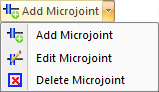
Add a microjoint between parts by clicking this option and then moving the crosshair cursor into the work area. Click on any snap point and the cursor will change to a small circle which will follow the outer perimeter of parts. Move the circle-cursor to the place between parts where the microjoint is to be placed and left-click to finalize.
Note: Enabling microjoints on a Common Cut will not apply lead-ins or lead-outs automatically; the user must enable them separately. Lead-ins/outs must be applied carefully, as there is a risk that they will cut into an adjacent part.
Edit
Select this option and then cursor into the work area. When the cursor gets near a microjoint it will snap to it and change into a small blue square. Left-click to open the Microjoint panel and make any necessary changes. Hit <Enter> to finalize changes or hit <Tab> to move to the next field.
Delete
Select this option and then cursor into the work area. When the cursor gets near a microjoint it will snap to it and change into a small blue square. When the square-cursor hovers over a microjoint, left-click to delete.
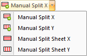
Using the Manual Split button, the user can add segments of Splits from the Common Straight Edge Cut to the part or sheet edge, or to the other Common Straight Edge Cut, which can be controlled as independent line patterns on the sheet for sequencing. (Compare this to the Split Sheet function, where splits are sequenced dynamically based on the relationship of the parts.) To delete split lines, hit one of the Processing options again.
Note: Be sure that Straight Edge Cut in the Common Cutting Settings dialog is selected.
Using Manual Split X/Y places a single split line on the perimeter that was clicked. Manual Split Sheet X/Y places a split that runs the width (or height) of the sheet.
By default, the split cut sequence will cut from part edge to sheet edge, and over or undercut according to a given value. To change split cut direction and over/undercut values, see Split Sheet Settings.
Manual splits can also be added between parts. When the user clicks on one point, AP100US will calculate the nearest point that intersects with the part/sheet boundary and splits the shorter line. For lines that have the same length, Y has the priority.
Note: Even if NO common cutting has been applied, manual splits can still take effect.

This option gives the user more control over sequencing splits placed by Straight Edge Cut or Common Cutting.
Click to auto-place splits on the sheet between parts.
This button is only active after parts have been processed. See Processing Options in Common Cutting for more info.