| Common
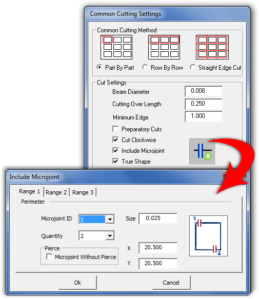
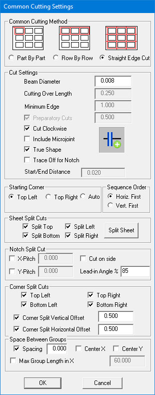
Cutting Settings allows you to specify your common cutting preferences.
Select Settings from the Common Cutting submenu
to display.
|
|||
 |
The
Common Cutting module is designed to calculate the most efficient
cutting of a sheet when parts share a common boundary. This option
takes effect on the external
boundary
of gridded/grouped parts. To control the cutting of internal cutouts,
see Machine Setting>Sequence
Info.
Use the options in this section to specify the preferred cutting method. Note: Settings and values appearing in this dialog are pulled from the Process Type>Custom Perimeter Cut panel (when Common Cutting is enabled). Changes made here are temporary, applying only to the current session in the AP100US program. Common Cutting settings in the Custom Perimeter Cut panel are not updated by changes made here (except for the Include Microjoint dialog described below). Changes made in this dialog to the Cut Settings remain in force until Apply/OK is clicked in the Process Type>Custom Perimeter Cut panel, at which point default values will override any temporary settings. Note: Common Cutting (part-by-part, row-by-row and straight common cutting) between different common cutting groups is supported. Note
on Grouping/Gridding Common Cutting Parts
|
||
Option |
Description
|
Common Cutting Method
|
|
Part By Part |
Use Part By Part if you want sequence one part before continuing onto the next part. When this option is selected, Bottom Left and Bottom Right options will be added to the Starting Corner settings. |
Row By Row |
Use Row By Row if you want to sequence a complete row of parts before processing the next row. |
Straight Edge Cut |
Used primarily for automation, selecting Straight Edge Cut allows AP100US to automatically detect and cut out perimeter notches first, before common cutting the overall part/group boundaries. The program supports a Straight Common Cut for multiple grids during nesting in Sheet Wizard. Note: When the user processes a straight common cut, it will not cut into the remnant portion of the sheet. |
Cut Settings |
|
Beam Diameter |
Type a beam diameter in this text box. The system will accept a beam diameter of 0 or above. |
Cutting Over Length |
Type the amount the system should overcut before starting or after ending a closed path. |
Minimum Edge |
Type the minimum distance that must be shared before the software will use preparatory cuts. |
Preparatory Cuts |
If you enable this option and type a length value in the text box to the right, the system sequences a series of preparatory cuts along the part perimeters. The system cuts the specified length of the adjacent part perimeter before processing the remainder of the part boundary. Note: This option is disabled when Straight Edge Cut is chosen.
|
Cut Clockwise |
If you enable this option, the common cutting is cut clockwise. If you remove the check mark, then common cutting is processed counter-clockwise. Note: This option is disabled when Row By Row is chosen.
|
|
|
Check this option to include microjoints. When the "Microjoint +" icon is clicked, the Include Microjoint dialog (shown below) displays. Enter standard information for the microjoint(s) for up to three ranges. The dialog shown here displays when either the Part By Part or Row By Row cutting method is selected. The system will add a pierce to a microjoint by default. Check the Microjoint Without Pierce to add a microjoint without a pierce. For more info on the other fields, see Material Info>Cutting Microjoints panel.
This
same dialog can be accessed in the
The
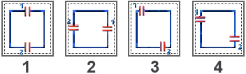
microjoint placement icon on the right can be
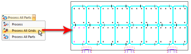
Apply Microjoints to Parts in a Grid When gridding the sheet and using either the Part By Part or Row By Row option, be sure to choose the Set Spacing [between parts] Equal to Beam Width option. After the grid is processed, the microjoints will be visible as in this image. See Cut Sequence tab>Common Cutting Module for more info.
Microjoints were applied to this grid using Placement Option #3
When Straight Edge Cut is selected, the CommonCut MJ dialog appears as shown here. In this dialog the user can specify microjoint Interval and Range in X/Y, microjoint size and whether or not to include a Pierce.
|
|
|
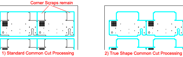
Parts that are processed with standard, common cut processing (image 1) may leave corner scraps in place, which can tilt on the shuttle table and hinder the part removing process. Check ON this option to allow True Shape processing for common cutting processing, as shown in image 2.
When preparing the sheet, if similar parts were gridded they should be converted to single rows or columns. (Converting to individual parts is not recommended.) See Grid for more info. In Cut Sequence>Common Cutting Settings be sure that the Spacing option is checked ON and a numeric value entered (such as 0.5). This space between rows (or columns) allows the system to process the common cutting row by row, or column by column. If preferred, the user may group the parts row by row or column by column using Sheet>Group Parts options.
|
|
|
Check this option ON to have the program place a G33 in the NC code on every corner notch, causing the laser head to maintain an even distance from the sheet while passing over a notch cutout (and updating the "CommonCut.ini" file in the C:\AP100US\Parm folder). Enter a Start/End Distance value to have the G33 kick in before the notch begins and hold until after the laser head passes. See Manual Trace off for more info.
|
Starting Corner |
The options in this section allow you to specify the start of the common cutting. When Part By Part is selected as the Common Cutting Method, the program allows Top Left, Top Right, Bottom Left or Bottom Right as choices. With Row By Row selected, only Top Left or Top Right are available. Straight Edge Cut allows Top Left, Top Right or No Preference (the program decides where to place the starting cut based on the location of the last cut).
|
Sequence Order
|
Select the sequence order for the sheet - Horizontal First or Vertical First. Horizontal makes all horizontal cuts first and them completes the vertical cuts; likewise, Vertical makes vertical cuts first, and then horizontal. This option is available only when the Straight Edge Cut cutting method is selected.
|
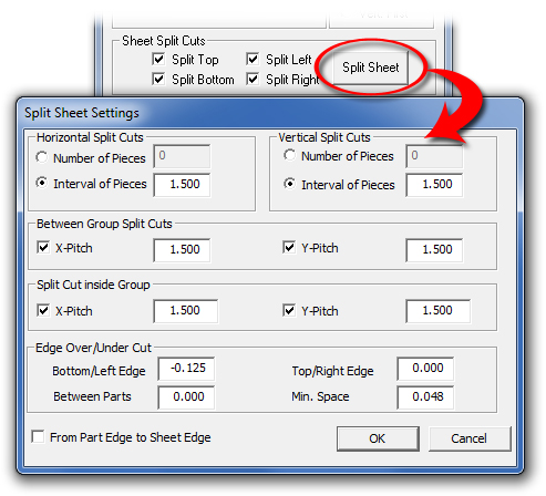
Sheet Split Cuts |
Select Split Top, Left, Bottom and/or Right to allow the system to place split cuts on the sheet. Click the Split Sheet button to configure the splits. This option is available only when the Straight Edge Cut cutting method is selected.
|
Click the Split Sheet button to open the Split Sheet Settings dialog shown here. After processing, the system automatically splits the sheet. For Horizontal and Vertical cuts select to cut the sheet into a specific number of pieces, or the size of the interval between cuts. Enter Between Group Split Cuts values to control the size of the pitch (space between splits) of split cuts in X and Y.
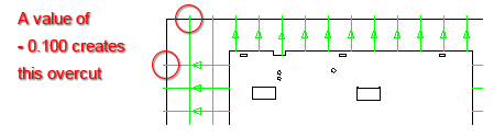
Note: This particular Split Sheet Settings dialog is only available through the Common Cut Settings submenu discussed on this page. These options only apply to groups that have been processed for Common Cut in Straight Edge Cut. A split cut created in this way is an actual pattern line segment on the sheet. (Compare this to the Split Sheet function, where splits are sequenced dynamically based on the relationship of the parts.) See Process Type>Custom Perimeter Cut tab for more Straight Edge Cut info. Edge Over/Under Cut allows the user to over-cut (Edge Over) or under-cut the edge of the sheet. Enter values for Bottom/Left Edge, Top/Right Edge and Between Parts. Min. Space is the value that the distance or interval between parts cannot be less than. Only when the space between parts is larger than the minimum space, will the split cut be placed between parts; otherwise it will not cut between parts. Select From Part Edge to Sheet Edge to cause the cut to begin at the part edge and run outward toward the edge of the sheet as shown by the direction of the arrows in this image -
A negative value of -0.100 allows the cut to extend one hundredth of an inch over the edge of the sheet. A value of 0.00 will cut to the very edge. Note: When Part by Part or Row by Row is the selected Cutting Method, this option is disabled.
|
|
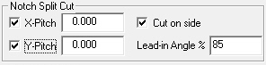
X-Pitch / Y-Pitch When processed by the system, Notch Split Cuts auto-splits notches on the parts. Pitch value is set in the above dialog box. These Notch Split Cut values will be synchronized to the Notch Split Cut option in Material Info>Process Type>Perimeter Notch Relief tab.
The values entered here are
dynamic
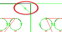
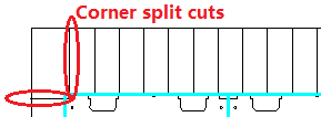
Note: When Part by Part or Row by Row is the selected Cutting Method, this option is disabled. Cut on side / Lead-in Angle Check ON this option to allow the program to cut notches on part corners when common cutting. When such corner notches are present, the program cuts them out first before doing the overall common cutting of the sheet. Use 85% as a standard lead-in angle, or another value.
The corner notch
is circled in red
|
|
Corner Split Cuts |
Corner split cuts can be automatically added at the four corners of the common path during the common cutting process. Offset value and location can be set manually in the setting UI. Select a corner and then select a Corner Offset and enter a value. The offset starts from the common path corner. It has no relationship with the sheet split cuts; only if corner split cuts are selected in the settings, will they added to the common path corners.
Sample of Corner Split Cuts Note: When Part by Part or Row by Row is the selected Cutting Method, this option is disabled.
|
Space Between Groups
|
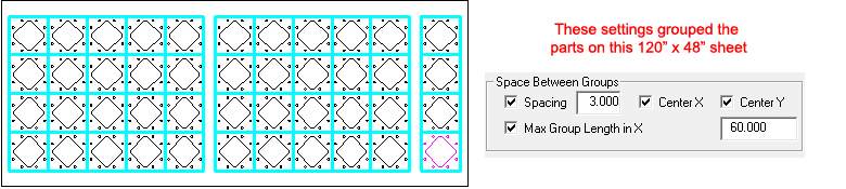
Check ON Spacing so that if two or more part groups (grouped before the common cut process) are on the sheet, when processing the straight common cut a space will be added between groups. This option is helpful when notches are on part perimeters and when using a part remover robot arm. If needed, check ON the Center X / Y options to center the groups on the sheet. It is only possible to set a space that is wider than the existing space. To set a space that is smaller, the parts on the sheet must be re-gridded. Note: When Part by Part or Row by Row is the selected Cutting Method, this option is disabled.
|
Use this feature to create evenly spaced part rows and groups on a sheet that is going to be common cut. This will provide greater stability for the sheet and reduce the risk of laser head having potential dive problems (or Z Alarm issues). For sheets that are long in the X, check ON this option to allow the system to place part rows in groups. Grid the parts while in the Sheet tab and select Set Spacing Equal to Beam Width in the Grid Properties window. Enter a value to set the maximum length for group and set Spacing as needed. In Cut Sequence>Common Cutting Settings select Process All Parts to prepare the sheet for common cutting.
|
|
OK
/ |
Click OK when you are satisfied with the settings and want to save them, or select Cancel to exit without saving any changes. |
|
When you setup the sheet, arrange the parts using the Grid, Move, or Align options on the Sheet menu. Make sure that the distance between parts you want to common cut is equal to that of the beam width. See Sheet for more info.
|
|
Note: For a grid of parts, use the Set Spacing Equal to Beam Width option in the Grid properties flyout window.
|