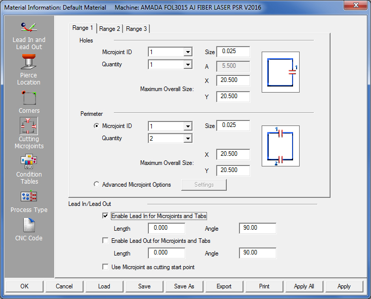
The options in the Cutting Microjoints panel allow the user to automatically place microjoints on the geometry, and define microjoint setups for both holes and perimeter patterns. A microjoint is considered an attribute and microjoints can be modified using options on the Sequence Features menu. When lead-ins and lead-outs are used with microjoints, the microjoint attribute actually consists of three elements. The End Cut Attribute is placed at the end of the geometry before the microjoint. The Microjoint Attribute is the actual microjoint, and the Start Cut Attribute is placed on the start of the lead-in after the microjoint. The software must also know the cutting direction before it can place a microjoint using the values from the Lead In/Lead Out folder.
The Cutting Microjoints panel is divided into three tabs. The tabs are subdivided into Holes and Perimeter sections. See Perimeter Range Checking. Each tab corresponds to a range for the automatic placement of microjoints. Each range contains the size of the microjoints, the quantity of microjoints and maximum overall size of the cutout.
The software first examines the Maximum Overall Size values for Range 1. If the overall size exceeds the maximum X and Y values for Range 1, then the system examines the values for Range 2. The system continues to examine the values until the cutout is checked using all three ranges. If the overall pattern size is greater than the X and Y values defined for Range 3, the software will not place microjoints on the pattern.
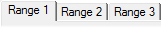
If the pattern falls within a specified range, the software applies the preset Quantity of microjoints (0 through 4) to the geometry. The software applies the microjoints to similar locations on the patterns. Click the placement toggle to position the microjoint on a hole pattern. If a quantity of 1 is selected, there will be four placement options as shown here -
A quantity of 2 has three placement options - Option three places microjoints near opposing corners. When this option is selected, the A field becomes active; enter a distance from the corner value. Quantity of 3 has four placements and quantity of 4 has one placement.
The options in the Perimeter section apply microjoints to the part perimeter or boundary. The options in this section function like those for Holes, but only Quantity values for 2, 4 or 6 microjoints are allowed. Specify three ranges, with each range containing the size of the microjoints, the quantity of the microjoints and the maximum overall size of the part perimeter.
The software compares the Maximum Overall Size X and Y values for Range 1, Range 2 and Range 3. If an overall perimeter size falls within a range, the preset Quantity of microjoints (2, 4 or 6) are applied to the part boundary.
This option gives the user more control over the size, quantity and placement of perimeter microjoints.
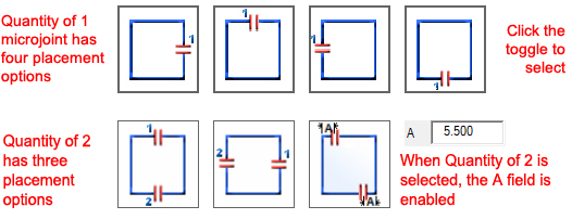
To enable and configure the option select the Advanced Microjoint Options radio button and then click Settings.
In the Range 2 tab, "A" represents the microjoint's distance from the edge of the part. Range 3 adds an additional microjoint that is auto-centered between the first microjoint and the opposite edge of the part. In Range 4, in addition to the first microjoint, two other microjoints are added, which are auto-centered between the first microjoint and the opposite edge of the part.
The Lead In/Lead Out panel in the Cutting Microjoints panel allows the user to control the application of Lead In and Lead Out lines to the microjoints and tabs. Tabs are placed on the corners of the part as Corner Attributes. The software automatically places a lead-in or lead-out on every microjoint and tab using the criteria from the Lead In/Lead Out folder.

To add Lead In or Lead Out lines, type the length and angle values in the respective text boxes. The upper pair of Length and Angle text boxes are for Lead In lines; the lower pair is for Lead Out lines.
Notes: If
Angle for a lead-in is set from 0 to 44, the system rounds it up to 45
degrees.
If an Angle is greater than 90, the system rounds it down to 90 degrees,
and if an Angle between 45 and 90 degrees, the system uses that actual
value.
This option will apply the Lead Ins for microjoints and tabs. Remove the check mark to suppress the application of lead-ins.
This option works independently from lead-ins enabled in the Lead In & Lead Out panel.
This option will apply the Lead Outs for microjoints and tabs. Remove the check mark in the check box to suppress the application of lead-outs.
This option works independently from lead-ins enabled in the Lead In & Lead Out panel.
Notes: The user can still use the interactive options Sequence Features menu to add or remove individual lead-ins and lead-outs.
The Lead In and Lead Out lines move in the same direction as that of the cut.
The Microjoint Lead In/Lead Out values are also applied to Tab corners.
By design the program will begin cutting at the location set in the Pierce Location Panel shown in image 1.
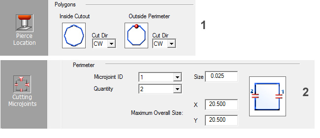
In image 2 in the Cutting Microjoints panel, the microjoints have been set on the vertical edge. Because the initial pierce and the microjoints are placed on different edges, this setting requires the program to make extra cuts. However, when the Use Microjoint as Cutting Start Point is checked, the cutting start point can be synchronized to the microjoint location, resulting in a cleaner edge and fewer redundant start points.
Note: This setting will change the pierce location when the part is sequenced, but the setting in the Pierce Location panel will not be changed.
Option |
Description |
OK / Cancel |
Click OK to keep any changes, or Cancel to close the window without saving.
|
Load |
Clicking the Load button displays the Open dialog box. If you want to change an existing tool inventory, use Open to load that tool inventory so you can make corrections. In addition to standard inv files, the user may choose to load from Tool Inventory files in .XLS or .CSV formats. From here it is also possible to create and edit .xls and .csv files. See Export below for more info on this.
|
Save |
To save
changes made to material files, click the Save button.
|
Save As |
To save
as an existing file that has been modified, click the Save
As button.
|
| Export | Clicking Export opens the Save As window and allows the user to export files in .xls and .csv formats. See Exporting Files in XLS or CSV formats in the Material Files folder for more info on creating and editing .xls and .csv files.
|
To print the Material Type window with entries in the Material Type and Comments fields, click the Print button.
|
|
Apply All / Apply |
Click Apply All to apply all changes made in this window. Click Apply to apply only the most recent change. |