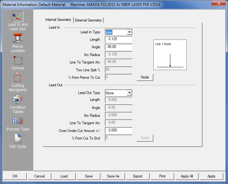
The Lead In/Lead Out panel allows the user to specify the lead-in and lead-out parameters for your materials. On this page learn about using the options on the Internal Geometry (Lead In) and External Geometry (Lead Out) tabs to define the lengths, angles and cutting conditions.
The lead-in/lead-out parameters defined for internal geometry are applied to the inside perimeters of the patterns, while those defined for external geometry are applied to the outside boundary of the parts.
Notes: If the radius of a pattern is less than the length of any Lead In type, the software applies a straight-line lead in from the center of the pattern. This includes Rounds, Obrounds, Single Ds, Double Ds, Rectangles, Squares, Triangles, etc.
Lead Ins are considered Start Cut Attributes and Lead Outs and Over/Undercuts are considered End Cut Attributes. Both of these options are found on the Sequence Features tab.
When loading a part, the Lead Ins and Lead Outs are placed automatically on the geometry. For cutting systems, the software internally adds the Lead Ins and Lead Outs when the part is loaded or when you create geometry. For combination systems, you must first assign the cutting tools before the system places the Lead Ins and Lead Outs on the cutting paths.
The system checks the geometry for interference problems after applying the Lead Ins. If a Lead In interferes with the actual part, or crosses over the path, the software will not process the cutout. The path changes to a red color and the AP100US System displays a warning message. You must manually solve the problem by either modifying the Lead In or relocating the starting point. The software will not sequence the path if the interference remains.
As the lead-ins and lead-outs are defined, the thumbnail graphic in the Display box updates to reflect any changes made to the values. The image here shows that a "Line & Arc" Lead In was selected. The "+ None" indicates that no Lead Out has been selected.
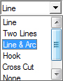
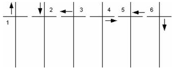
There are six lead-in types: Line, Two Lines, Line and Arc, Hook, Cross Cut and None. The lead-in selected is used as the default for all the geometry on the part. Choose an alternate lead-in type by selecting the appropriate option button.
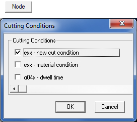
Note: Checkboxes in this dialog may differ, depending upon the driver loaded. |
|
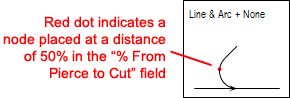
Click the Node button to open the Cutting Conditions window. Check ON Cutting Nodes to be placed along the Lead Ins and Lead Outs. When placed, a node appears as a red dot on the lead-in line. The options in the Cutting Conditions window are dependent on the machine driver. To enable a cutting condition, place a check mark in its check box. If necessary, type a value in the text box that becomes available after selecting the option. Node Locations For a Lead In type, you express the actual node location as a percentage from the Start Point. For example, to place a node at the midpoint of a lead-in, you would type 50 in the % From Pierce to Cut text box, thereby indicating a distance of 50%. For a Lead Out type, the Node value is derived from the end of the geometry or the start of the Lead Out line. To specify the value, you would type a number in the % From Pierce to Cut text box. Notes: A node must be placed on the Lead-In/Out in order to activate the % From Pierce To Cut field. The system will not allow a value greater than 100 to be set for the Node percentage. |
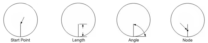
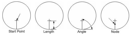
The Line Lead In is the default selection. It consists of a straight line that can be set to any angle. For a Line Lead In, only the Length, Angle and Node options are available. The illustrations below depict the variables that can be specified for the Line Lead In.
The Start Point is derived from the Length and Angle relative to the geometry. The Length is the distance from the geometry to the Start Point of the Lead In. The Angle is a value, expressed in degrees that the Lead In will be from the geometry. The cutting direction determines where the Angle begins from the geometry to the Start Point. The Angle is consistent relative to the position of the geometry.
The Node location is expressed as a percentage from the Pierce point down towards the geometry. The illustrations depict Lead Ins at different positions using a Length of 0.250 at an Angle of 35º. Notice the different cutting directions. The angle shifts, but remains the same angle. The Lead In moves in the same direction as the cut.
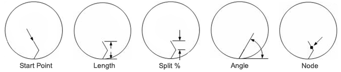
The Two Lines Lead In allows the user to lead into a path using two lines. For a Two Lines Lead In, the Length, Angle, Node and Two Line Split % options are available. The illustrations depict the variables that can be specified for the Two Lines Lead In.
The Start Point is derived from the total Length of the two line segments. The Length is the distance from the geometry to the Start Point of the Lead In. The Angle is a value, expressed in degrees that the Lead In will be from the geometry. The cutting direction determines where the Angle begins from the geometry to the Split Point.
The Angle is consistent relative to the position of the geometry. The Split value is a percentage from the Start Point to the path. The software takes the value entered in the Two Line Split % text box and splits the two lines from the Start Point to the path. The Node location is expressed as a percentage from the Pierce point down towards the geometry.
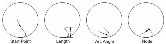
The Line and Arc Lead In type consists of a pierce line with a lead-in arc. The Start Point is derived from the total Length of the pierce line and the lead-in arc. The Length is the distance from the geometry to the Start Point of the Lead In. The software derives the Node location using the entire lead-in, i.e., the pierce line and arc, to calculate the percentage from the Start Point. The Node distance is calculated using the total length of the Line and Arc.
For a Line and Arc Lead In, the Length, Node and Line to Tangent Arc options are available. The illustrations depict the variables you can specify for the lead-in.
Note: The Line to Tangent Arc value cannot be set to a value greater than 90 degrees.
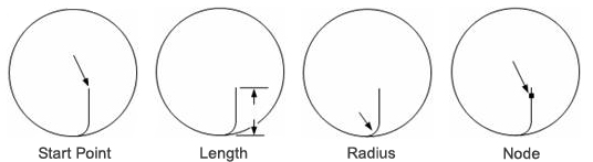
The Hook Lead In is similar to the Line and Arc type, but the pierce line is always perpendicular to the Start Point of the path. The arc angle and line angle remain at 90 degrees. These images depict the variables that can be specified for the Hook Lead In. For a Hook Lead In, the Length, Node, Arc Radius and % From Pierce to Cut options are available.
The Start Point is derived from the total Length value of the pierce line and radius. The Length value is the total distance from the geometry to the Start Point of the Lead In. The value includes the radius of the arc and the length of the pierce line. The Radius is the actual radius of the arc. If a Radius value is specified that is greater than the Length value, the software displays an error message. The software derives the Node location using the entire lead-in, i.e., the pierce line and arc, to calculate the percentage from the Start Point.
Cross Cut lead-ins are usually employed for thicker materials. Some laser systems use a Cross Cut lead-in as a standard routine. The Cross Cut lead-in allows the laser beam to penetrate completely through the material before the cutting head reaches the geometry. The Cross Cut is similar to the Line lead-in, but the cross is cut from the Start Point. For a Cross Cut Lead In, the Length, Angle, Node and % From Percent to Cut options are available. The illustrations depict the variables that can be specified for a Cross Cut Lead In.
The Start Point is derived from the Length of the line to the intersection of the cross. The Length value is the total distance from the geometry to the Start Point or the intersection of the cross. The Angle is a value, expressed in degrees that the Lead In will be from the geometry. The cutting direction determines where the Angle begins from the geometry to the Split Point. The Angle is consistent relative to the position of the geometry. The Node percentage value is derived from the Start Point. The Node is always placed below the intersection of the cross.
The following graphic depicts the direction and order of the cross cut. The cross begins at the Start Point and moves away from the geometry that is 1/3 the Length value. When the cross is complete, the system will lead straight into the cut.
The None Lead In type starts the cut directly on the path. When this option is selected, the remaining fields in the Lead In Type section are disabled.

There are four lead-out types: Line, Arc, Line and Arc and None. The lead selected is used as the default for all the geometry on the part. Choose an alternate lead-out type by selecting the appropriate option button.
Note: Using lead-outs on internal cutouts depends on material type and thickness; however, lead-outs are typically used on material 1/8" or more in thickness.
The Line Lead Out allows the user to define a lead out of the geometry with a line at any angle from 0ºto 180º. An angle greater than 180º may cause interference. For a Line Lead Out, only the Length, Angle and Node options are available. To achieve a continuous cutting flow, specify an angle between 90º and 180º. The cutting direction affects the angle of the Lead Out.
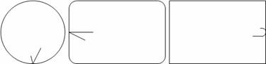
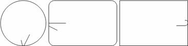
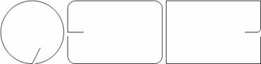
The following graphic depicts Lead In and Lead Out lines on an internal cutout. The image on the left shows that the user chose a Hook lead-in and a Line lead-out. Images 1 and 2 show how the cut begins on the Lead In and proceeds to cut out the perimeter. When the laser head finishes cutting out the pattern, it turns inward away from the perimeter to complete the Lead Out as shown in image 3.

Lead In and Lead Out lines are
shown longer than usual for visual effect
The Arc Lead Out allows the user to place a circular lead out at a specified angle on the geometry. For an Arc Lead Out, only the Arc Radius and Line To Tan (Tangent) Arc options are available. The cutting flow is continuous; the arc continues cutting in the direction from the end of the cut. The direction of the cut affects the angle of the Arc Lead Out.
The Line and Arc Lead Out consists of a lead out arc and line. You must specify values for the Length, Arc Radius and Line to Tan (Tangent) Angle. The software calculates the tangent angle to the end of the arc. The Line and Arc Lead Out travels in the same direction of the cut. The respective Lead In lines are 30º. The Line and Arc Lead outs consist of 75º arcs with lines that have a length of 0.125.
The None Lead Out is the default selection. The remaining fields and values in the Lead Out Type section are unavailable. The software will not place any lead-outs on the geometry.
The Over/Under Cut Amount +/- option allows the user to control the end of each cut. The value typed in the text box determines the extent of the overcut or undercut. The default value is zero. If the value is zero, the cut will end where it started. If a positive value is entered, the cut extends beyond the starting point by the specified amount. If a negative value is entered, the cut stops short of the starting point by that amount.
|
|
|
|
Default of Zero |
|
|
The cut ends where started. |
|
|
Positive Value |
|
|
The path is overcut. |
|
|
Negative Value |
|
|
The path is undercut. |
Option |
Description |
OK / Cancel |
Click OK to keep any changes, or Cancel to close the window without saving.
|
Load |
Clicking the Load
button displays the Open dialog box. If you want to change an
existing tool inventory, use Open to load that tool inventory
so you can make corrections.
|
Save |
To save changes made to material files, click the Save button. See Save for more info.
|
Save As |
To save as an existing file that has been modified, click the Save As button. See Save As for more info
|
| Export | Clicking Export opens the Save As window and allows the user to export files in .xls and .csv formats. See Exporting Files in XLS or CSV formats in the Material Files folder for more info on creating and editing .xls and .csv files.
|
To print the Material Type window with entries in the Material Type and Comments fields, click the Print button.
|
|
Apply All / Apply |
Click Apply All to apply all changes made in this window. Click Apply to apply only the most recent change. |