Users may customize the Ribbon Interface by changing icon style and placement.
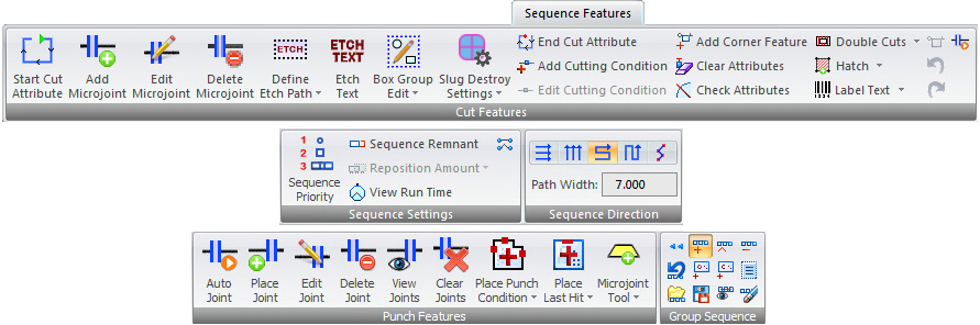
Sequence Features Ribbon tab
Users may customize the Ribbon Interface by changing icon style and placement.
|
|
|
|
To modify the start point of a path, select Start Cut Attribute.
Click for more Start and End Cut Attribute Options info. |
|
To add a microjoint to a cutting path, select Add Microjoints.
Click for more Cut Microjoint Options info.
|
|
To modify the microjoint attributes, select Edit Microjoints.
Click for more Cut Microjoint Options info.
|
|
To delete a microjoint, select Delete Microjoint.
Click for more Cut Microjoint Options info. |
|
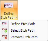
Open the flyout menu to display Etching options.
Click for more Etch Options info.
|
|
The Etch Text option allows you to create and generate an etch path and assign a cutting condition to the text.
Click for more Etch Options info.
|
|
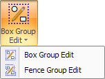
Open the flyout menu to display Box Group Edit options.
Click for more Group Editing Features info.
|
|
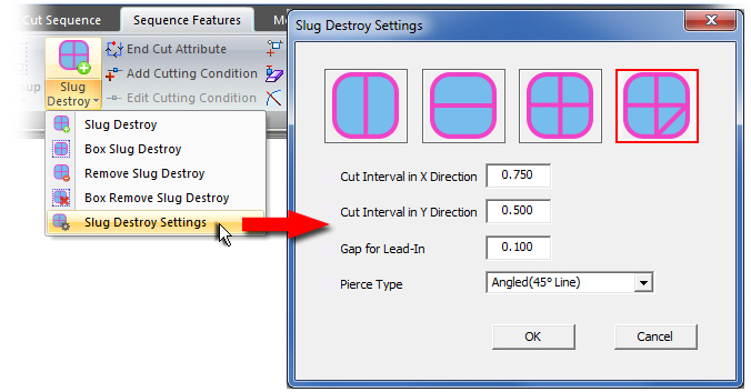
Slug Destroy options in this pull-down menu allow the user to manually apply Slug Destroy to specific patterns for the current session only. To automatically apply Slug Destroy and for complete info on the option, see the Slug Destroy page.
Slug Destroy manually assigns Slug Destroy to any closed loop that is clicked.
Box Slug Destroy manually assigns Slug Destroy to all closed loops within a rectangular selection area defined by the user. The user must drag out a box that encloses patterns with slugs.
Remove Slug Destroy manually deletes a Slug Destroy assignment, one at a time by left-clicking.
Box Remove Slug Destroy manually deletes the Slug Destroy assignment from all of the closed loops within the rectangular selection area defined by the user.
Slug Destroy Settings Options in this window allows the user to configure "in session" Slug Destroy settings that are used when Slug Destroy is manually assigned to patterns.
For info on these settings see Slug Destroy.
By default, Slug Destroy pulls its values from the settings in the Slug Destroy tab in the Material File. However, during manual assign, changes made by the user will over-ride any other (default) settings and take effect for the next Slug Destroy assignment.
Note: Whenever Slug Destroy is assigned automatically, via Apply in Material File, Sheet Wizard, etc. the software will use the settings from Slug Destroy in the Material File.
|
|
To modify the end point of a path, select End Cut Attribute.
Click for more End Cut Attribute info. |
|
If you need to apply a cutting condition along a path, select Add Cutting Condition.
Click for more Cut Condition Options info.
|
|
If you need to modify a cutting condition along a path, select Edit Cutting Condition.
Click for more Cut Condition Options info.
|
|
To place features on part corners, select Add Corner Features.
Click for more Cut Corner Feature Options info.
|
|
The Clear Attributes option allows you to select which type of attribute you want to remove from the part.
Click for more Clear Attributes info.
|
|
To determine whether cutting attributes or pre-punch tools invade the geometry of other patterns or parts, select Check Attributes.
Click for more Check Attributes info.
|
|
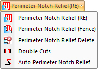
Certain notches and cutouts can "catch" when the part remover attempts to remove the part. Options here can apply additional cuts to a takeout that can free up these problem areas of a part.
Click for more Process Type>Perimeter Notch Relief info.
|
|
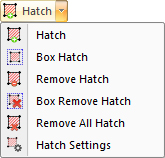
The Hatch Etching option on the Sequence Features tab allows the user to create decorative designs and text on a part by etching out specified surface areas in a pattern.
See Hatch Etching for more info. |
|
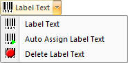
To assist users in tracking production parts during the manufacturing process, text may now be placed on a part using simple interface commands. Labels with text and an auto-generated barcode may be placed on individual parts, or all the parts on a sheet.
Note: This option is driver-dependent; it can only be used with a PSR machine and will not appear or may not be active if the correct driver is not loaded.
See Label Text for full info.
|
|
To edit features on part corners, select Edit Corner Features.
Click for more Cut Corner Feature Options info.
|
|
To reverse the last attribute modification, select Undo Attribute. To repeat the last attribute modification, select Redo Attribute.
Click for more Undo / Redo Attribute info.
|
|
The Auto Microjoint option on the Cut Microjoint submenu will automatically place microjoints using the parameters you have specified.
Click for more Cut Microjoint Options info.
|
|
|
|
|
Select Sequence Priority and the Tool Sequence window appears, listing all the tools and sequence groups assigned to the sheet.
See Tool Sequence Priority window for more info.
|
|
The Sequence Remnant option allows you to create a remnant sheet that you can store in the Material Inventory for nesting.
Click for more Sequence Remnant info.
|
|
Select to allow the system to enable Auto Reposition. The system will automatically perform repositions when required during Auto Sequence.
Click for more Auto Reposition info.
|
|
Click View Run Time in the Sequence Features menu to estimate project run time.
Click for more View Run Time info.
|
|
The Edit Trace Line option allows you to manually alter the travel over the sheet.
Click for more Edit Trace Line info.
|
|
|
|
Sequences the part/sheet in x line-by-line.
Click for more Sequence Direction info.
|
|
Sequences the part/sheet in y line-by-line.
Click for more Sequence Direction info.
|
|
Sequences the part/sheet in x.
Click for more Sequence Direction info.
|
|
Sequences the part/sheet in y.
Click for more Sequence Direction info.
|
|
Sequences the part/sheet in the shortest possible path.
Click for more Sequence Direction info.
|
|
When sequencing in x or y is selected, this field becomes active. If necessary enter a temporary Path Width that will override the default path width set in Machine Settings>Sequence Info>Sequence Direction.
|
|
|
|
The Auto Microjoint option will automatically place bridge and corner microjoints using the parameters you have specified.
Click for more Auto-Place Microjoint info.
|
|
The Place Microjoint option allows you to manually place bridge microjoints along the part boundaries, arcs, lines, C-notches and V-notches.
Click for more Manually Place Joint info.
|
|
To modify a microjoint after you have placed it, select Edit Microjoint.
Click for more Edit Joint info.
|
|
To remove a punching microjoint, select Delete Microjoint.
Click for more Delete Joint info.
|
|
To see punching microjoints, select View.
Click for more View Joints info.
|
|
To remove bridge and corner microjoints, select Clear.
Click for more Clear Joints info.
|
|
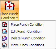
A punching condition is a machine operation that you assign to a pattern. Open the flyout menu to place punch conditions.
Click for more Punch Condition Options info.
|
|
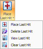
This option allows you to select a part instance for sequencing the last tool hit within the current sequence group.
Open the flyout menu to place last hit.
Click for more Last Tool Hit Options info.
|
|
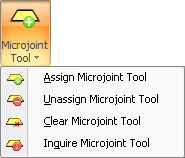
Open the flyout menu to see other commands for microjoint tools.
Click for more Microjoint Tool info.
|
|
|
|
Select to reset the current sequence group list. Click for more Group Sequence Functions info.
|
|
Select to add a sequence to the current group. Click for more Group Sequence Functions info.
|
|
Select to insert a sequence into the current group. Click for more Group Sequence Functions info.
|
|
Select to remove a sequence from the current group. Click for more Group Sequence Functions info.
|
|
Select to reverse the last action performed with the Add, Insert or Remove options within the current sequence group. Click for more Group Sequence Functions info.
|
|
This option allows you to select a part instance for sequencing the last tool hit within the current sequence group. Click for more Group Sequence Functions info.
|
|
This option allows you to sequence all the remaining patterns within a sequence group that share the same tool. Click for more Group Sequence Functions info.
|
|
To define a sequence group, select Group to open the New Sequence Group Name dialog box. Click for more Working with Sequence Groups info.
|
|
Select Load, and the Load Sequence Group window opens to allow you to load sequence groups to view or edit them. Click for more Working with Sequence Groups info.
|
|
Select to save a group. Click for more Working with Sequence Groups info.
|
|
Select to view a previously created group sequence. Click for more Working with Sequence Groups info.
|
|
Select to delete a sequence group. Click for more Working with Sequence Groups info.
|