Cut Microjoint
Options
Use the Auto Microjoint, Add Microjoints, Edit
Microjoints and Delete Microjoint
options to add microjoints to cutting paths and modify or delete existing
microjoints.
 The
Auto Microjoint option on the Cut Features submenu will
automatically place bridge and corner microjoints using the parameters
you have specified in the Cutting Microjoints panel of the Material Information
window.
The
Auto Microjoint option on the Cut Features submenu will
automatically place bridge and corner microjoints using the parameters
you have specified in the Cutting Microjoints panel of the Material Information
window.
If
your machine is equipped with a MJC (Micro Joint Cutter) device, you can
choose whether to have the joints processed by the machine. Click Yes
in
the dialog, the
joints will be cut by the MJC device. The system will determine the joint
type (corner joint, bridge joint, special tool joint) and angle automatically.
Click No to have the
system will use the designated relief tool in the turret to cut the microjoints,
or adjust the tools along the paths using the parameters in the Punching
Microjoints panel to create the microjoints.
 To add a microjoint to a cutting path, while in Part view select
Add Microjoints from the Cut Features submenu. Move into
the work area. Move the pointer to position the cutting microjoint along
the length of the pattern. If you want to choose a different pattern,
click the right mouse button. Select the correct pattern and click the
left mouse button. The positioning marker hesitates at the snap points
so you can easily select the point. The Microjoint flyout window appears.
You can specify the properties of the microjoint(s) at this point, or
edit the microjoint(s) using the Edit Microjoints option.
To add a microjoint to a cutting path, while in Part view select
Add Microjoints from the Cut Features submenu. Move into
the work area. Move the pointer to position the cutting microjoint along
the length of the pattern. If you want to choose a different pattern,
click the right mouse button. Select the correct pattern and click the
left mouse button. The positioning marker hesitates at the snap points
so you can easily select the point. The Microjoint flyout window appears.
You can specify the properties of the microjoint(s) at this point, or
edit the microjoint(s) using the Edit Microjoints option.
 To modify
the microjoint attributes, when in Part view select Edit Microjoints
from the Cut Features submenu. Move into the work area. The pointer
toggles between the microjoints. When you click a microjoint, the Microjoints
flyout window appears and activates the interactive edit mode.
To modify
the microjoint attributes, when in Part view select Edit Microjoints
from the Cut Features submenu. Move into the work area. The pointer
toggles between the microjoints. When you click a microjoint, the Microjoints
flyout window appears and activates the interactive edit mode.
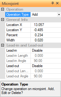
Whenever you add or edit
cutting microjoints, the Microjoint flyout window appears.
The window contains options that allow you to modify the attributes
of the selected microjoint, such as the width and the lead-in
or lead-out properties. |
|
Option |
Description |
Operation
Type |
There
are three options you can select from the drop-down list:
Add, Edit and Delete. |
Add |
The
Add option will appear by default when the system is in
Add Microjoints mode. Select Add from the Operation Type
drop-down list if you want to add microjoints, rather
than edit or delete microjoints. The system remains in
Add Microjoints mode until you select another option. |
Edit |
The
Edit option will appear by default when the system is
in Edit Microjoints mode. Select Edit from the Operation
Type drop-down list if you want to modify the microjoints,
rather than add or delete microjoints. The system remains
in Edit Microjoints mode until you select another option. |
Delete |
Select
Delete from the Operation Type drop-down list if you want
to remove microjoints. You can then move into the work
area and select those microjoints that you want to remove
from the patterns. The system remains in Delete Microjoints
mode until you select another option. |
General
Info |
This
section of the Microjoints flyout window displays
general information about the selected microjoint. |
Location
X |
This
field displays the X coordinate of the microjoint. A new
location button appears to the right of the
field when you select the label, allowing you to modify
the X coordinate of the microjoint. |
Location
Y |
This
field displays the Y coordinate of the microjoint. A new
location button appears to the right of the field
when you select the label, allowing you to modify the
Y coordinate of the microjoint. |
Percent |
The
paths on which you place microjoints are considered sets
of individual segments (line segments and arc segments).
The value that appears in this field represents the distance
of the microjoint from the beginning of the current segment
(this is not the distance from the start point of the
path). You can type a number to alter the position of
the microjoint. |
Width |
This
field displays the width of the microjoint. You can type
a new value to modify the width during either Add Microjoints
or Edit Microjoints mode. |
Lead-In
and Lead-Out |
The
options in the Lead-In and Lead-Out section of the Microjoints
window allow you to control the application of lead-in
and lead-out lines to the microjoints. The software automatically
places a lead-in or lead-out on every microjoint using
the settings from the Lead In/Lead Out section in the
Cutting Microjoints panel of the Material Information
window. |
Lead-in |
To
apply a lead-in line to the microjoint, select Enable
from the Lead-in drop-down menu. Select Disable from the
drop-down menu to suppress the application of a lead-in
line to the microjoint. |
Lead-in
Length |
Type
a length value for the microjoint lead-in line. |
Lead-in
Angle |
Type
an angle value for the microjoint lead-in line. |
Lead-out |
To
apply a lead-out line to the microjoint, select Enable
from the Lead-out drop-down menu. Select Disable from
the drop-down menu to suppress the application of a lead-out
line to the microjoint. |
Lead-out
Length |
Type
a length value for the microjoint lead-out line. |
Lead-out
Angle |
Type
an angle value for the microjoint lead-out line. |
|
Delete Microjoint

When
in Part view, left-click the icon and the cursor will be come a blue box
that snaps to the nearest microjoint when moved into the work area. Left-click
to delete.