![]()
Slug Destroy is a powerful feature that enables the user to specify the slugs that will be destroyed. and set parameters for how the slugs themselves will be cut up.
Open this window by going to the System Setting>Edit Material>Process type tab
Note: If Slug Destroy does not appear in the menu tab, enable the option by going to the C:\AP100US\Parm folder and double-clicking the AutoSplitHole.ini file to open it. If the Split Hole Mode is set to 1, enter <0> to switch it OFF and then save the file. Restart the program and Slug Destroy should appear in the menu.
| Slug Destroy Assignment
to Inner Cutouts
This section regulates the overall size and type of patterns that will be targeted by Slug Destroy. Options in this panel can be saved as default settings by clicking the Save button. Clicking OK keeps the settings for the current AP100US session. |
|
| Do not apply Slug Destroy to Inner
Cutouts
Selecting this option will disable Slug Destroy and the option will not be applied to any cutouts. This is the default setting. |
|
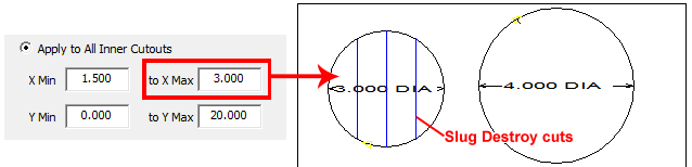
| Apply to All Inner Cutouts
Enter Minimum and Maximum size ranges for X and Y. All internal closed loops that fall within the specified size range will be destroyed. Range-checking and validation applies to these text boxes. Values cannot be negative. Max size for cutouts in X is set to 3.0, so the 4.0 Round Pattern was ignored |
|
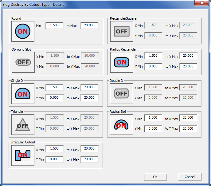
| Apply Based Upon Cutout Type and
Size
The user may select which pattern types and sizes Slug Destroy will be applied to. Select the option and then click the Details button to open the Slug Destroy by Cutout Type - Details window, shown here -
Irregular Cutout includes non-standard shapes and special tools. |
|
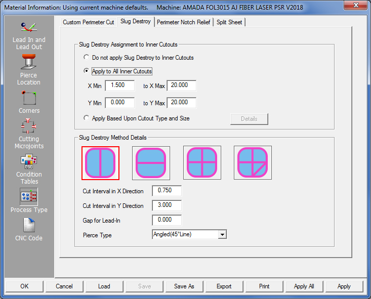
Slug Destroy Method Details
This section gives the user fine control over the slug destroy cuts and the size/shape of slug scraps that will be created. The size of slug scraps will never exceed the value entered by the user. However, the program will determine and adjust the width and quantity of Slug Destroy cuts, so that the fewest number of cuts will be made.
 |
Vertical Slug Destroy will
make slug destroy cuts in the vertical. This option is
useful
for making cutouts fall through the Cutting Plate (for sheet-draggers
such as Pulsar, EML & LCC1). This will make a series of vertical
Slug Destroy Cuts, with the final Slug Destroy Cut continuing
on to cut out the perimeter of the Inner Loop. Enter a
Max
Slug Size - X Direction to
control spacing between vertical cuts.
|
|
 |
|
Horizontal Slug Destroy will make slug destroy cuts in the horizontal. This will make a series of horizontal Slug Destroy Cuts, with the final Slug Destroy Cut continuing on to cut out the perimeter of the Inner Loop. Enter a Max Slug Size - Y Direction to control spacing between horizontal cuts. |
 |
Grid Slug Destroy This will make a series of horizontal and vertical Slug Destroy Cuts, with the final Slug Destroy Cut continuing on to cut out the perimeter of the Inner Loop. Enter a Max Slug Size in X & Y Direction to control spacing between horizontal cuts. | |
 |
Continuous Slug Destroy will also make slug destroy cuts in a grid pattern, but when applying the method, the base assignment pattern begins with grid lines and then connecting cuts are added to make the cutting continuous. Note: When Continuous Cutting is applied by software and the "continuous" paths end up cutting across/through "good" sections of the part, then the program will automatically revert to the Grid method. |
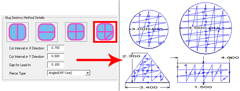
Slug Destroy settings on the left give these
results on the patterns
(Gap for Lead-in value has been exaggerated for visual effect)
Cut
Interval in X/Y Direction
For the X direction,
enter a cut interval value (the distance between cuts). For the Y direction,
enter a cut interval value. When using Grid Slug Destroy, enter values
in both X & Y fields.
Gap
for Lead-In
This value allows the
user to fine tune the laser cut lead-in, in order to compensate for beam
diameter and other considerations that are unique to the machine in use.
The software will already compensate the Pierce Location of each
Slug Destroy Cut by the Beam Diameter, if a Beam Diameter value has been
entered elsewhere in Machine Settings. If it is set to 0.000, then
the Pierce will occur directly at the edge of the feature, compensated
solely by the Beam Diameter entered by user.
See Pierce Location panel for more info on Beam Diameter and Lead-In, Lead-Out for more info on Lead-Ins.
Pierce
Type
For the three types
of Lead-ins, the Lead-In length will be the value entered in the Material>Lead In & Lead Out
panel.
At Edge (No Lead-in)
For this pierce type the software will
pierce directly at the Slug Destroy cut line, only compensating for the
beam diameter. If there is a value in "Gap for Lead-In",
then there will be an additional compensation by the amount the user specified.
(ex: .006" Beam Diameter + .010" Gap for Lead-in Value
would result in 0.013" compensation pierce location)
Note: For Horizontal, Vertical, and Grid Methods, the final Slug Destroy cut will continue onwards to complete the cutting of the entire feature.
Angled (45° Line)
This Lead-in type will be a 45° line,
of the same length that the user has defined in the Material>Lead
In & Lead Out panel.
If a collision with the Lead-in is detected into the part, the software will attempt to flip the lead-in by 90 degrees (to the other side of the line, to remove the collision. If a collision cannot be resolved by rotating the lead-in angle, then that Slug Destroy Cut will be an At Edge (No Lead-In) pierce.
From Center Outwards
This Lead-in type will consist of a
central pierce, in the middle of the Slug Destroy Cut Line, and cutting
will occur from this central Pierce Location outwards in each direction
towards the edges of the cutout.
Slug Destroy Settings Mini-window
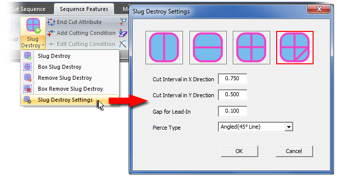
The main Slug Destroy window & the Mini Settings
window are dynamically linked
Updates done in one Input area will simultaneously appear in the other
Access the Slug Destroy pull-down menu to apply or remove Slug Destroy from patterns on an individual basis while in the work area. Open the mini-window to open a scaled-down version of the settings available in Process Type>Slug Destroy tab.
Note: The Slug Destroy option may be switched OFF, in favor of the Split Cutouts option. See Split Cutouts for more info.