Note:
The Cutting panel itself is only available if a cutting or combo machine
is currently loaded.
The Split Cutouts
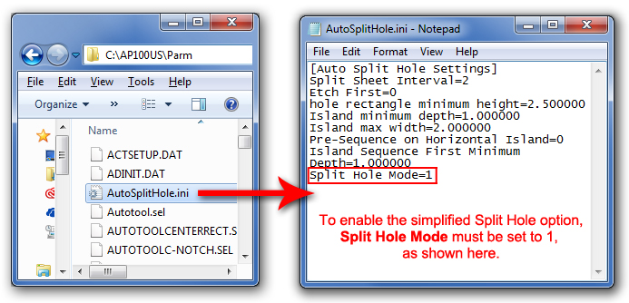
submenu is switched OFF by default and does not display. To switch it
ON, go to the C:\AP100US\Parm folder and double-click the AutoSplitHole.ini
file to open it. The Split Hole Mode is set to 0 by default. Enter <1>
to switch it ON and then save the file. Restart the program and then check
ON the Enable Auto Split Menu
switch in Preferences>Cutting. The
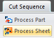
Split Cutouts (Hole) submenu will then appear in the Cut Sequence tab.
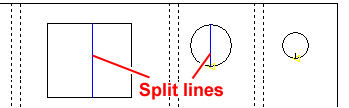
Similar
to the Split Sheet function, the Split Cutout option allows the user to
cut internal slugs into smaller sections in the X/Y directions to allow
them to fall through the slats of the shuttle table. There's no need to
reset the cutting sequence, because when the user places a split hole
cut, the system will automatically include this in the existing sequence.
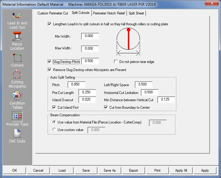
In
the Process Type window, open the Split Cutouts tab and
place a check in the Lengthen Lead-In to split cutouts
and/or other check boxes as in the image -
|
|
Min Width |
Enter a value
to control the minimum
size that the system will split in half. Any cutout that is smaller
than this value will remain uncut.
To ascertain
the size of cutouts use options on the Dimensioning
menu.
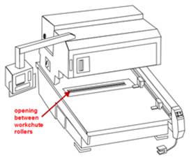
Note: Generally
a cutout that is one inch or smaller doesn’t need to be split,
as it will easily fall between the workchute rollers.
|
Max Width |
Enter a value
to control the maximum
size that the system will split. Any cutout larger than this value
will remain uncut. Larger cutouts should be split, so choose a
value that takes in to account the largest cutout on the part.
Note: If
the cutout is not a standard shape (irregular), then the overall
bounding width (in X) of the rectangle is used to determine if
that cutout should be split or not.
|
Slug Destroy Pitch |
Enable
the checkbox and enter a value to destroy internal cutout slugs
as in the illustration. This option may be used together with
Lengthen Lead-In. This option also takes effect when Fast
Cutting.
Note:
Length and angle values for lead-ins and lead-outs (if used) on
internal cutout slugs are pulled from the Lead In / Lead Out section
on the Split Sheet tab. To avoid
cutting into the part itself, be sure to check the length and
angle values for the lead-in/out carefully!
|
Do not pierce near edge |
To avoid
having the program pierce a cutout on its edge, check this box.
1)
The pierce will begin at the center of the cutout (a lead-in property
may be enabled in Split Sheet),
move down in the Y towards the edge of the cutout and stop short
of the perimeter (by a distance which equals the internal lead-in
geometry length).
2)
A second cut (no pierce) moves up in the Y and stops short of
the perimeter (distance equals the beam diameter value).
3)
The last cut pierces near the bottom (lead-in
may be applied) and then finishes cutting out the slug along the
cutout perimeter.
Note:
Slug Destroy Pitch must be switched on for this feature to work.
|
Remove Slug Destroy when
Microjoints are Present |
When
this is checked ON, if the system detects microjoints on a cutout,
it will bypass the microjoints and leave them intact and functional,
while cutting out the remainder of the slug.
|
| Auto
Split Setting |

|
The
Auto Split Setting dialog shown here is identical to the one accessible
by clicking the gear icon on the Cut Sequence>Split Cutouts
submenu.
|
|
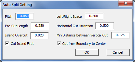
Note: Options outlined
in this dialog are generally used for
lightweight materials (ex: aluminum, 20 gauge or less) and
allow the user to place very small and precise split cuts.
|
|
Pitch: This controls the distance
between splits in the cutout.
Left/Right Space: Distance from
the edge of the hole on both left and right sides of the cutout.
Pre-Cut Length: Very thin gauge
materials sometimes require a centrally located vertical precut
before other vertical cuts can occur.
Horizontal Cut Limitation: This
option is used when there are vertical split lines, which have
been cut into smaller line segments. If the lengths of the vertical
cuts are shorter than the user-entered value, horizontal pitch
cuts between vertical cuts will not be cut.
Island
Overcut: This value controls
the size of the overcut when cutting the remaining boundary on
an island. It takes affect only when Cut Island First is checked ON.
Min
Distance between Vertical Cut: This
value is the minimum distance between the vertical boundary and
the split line in the vertical direction.
Cut Island First: If an island
exists on the part, the system will cut it out first. Check the
box ON to enable this option.
Cut from Boundary to Center:
If pre-cuts have already been cut, full cuts will start at the
edge of the hole and move toward the center.
Click
OK to save or Cancel
to close out the dialog without saving any changes. |
|
|
Beam
Compensation
|
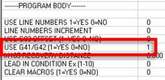
Use value from Mat. File |
The value in
this read-only field is entered in the Pierce
Location>Cutter Compensation fields. This option is
typically selected when the G41/42 code is switched OFF (0) in
the CNC Code panel,
because the user requires more control over the cutout. Be sure
to specify exact values to ensure accurate cuts.
|
Use Custom value |
Enter a value here
for Beam (width) Compensation. Use this option when the G41/42
is switched ON (1), which allows the system to automatically calculate
beam compensation.
Note: The
driver divides the entered value in half and adds or subtracts
it from the actual geometry.
|
|
Further Notes:
This
function only applies to paths that cut on the in-side; If
there is Microjoint on the cutout, the system will not split
the cutout; This
function does not apply if another part is nested within the
cutout; Split
Cutouts cuts from the downside to up, so the pierce location
will be at the bottom of the cutout.
|
|
|
To save and
apply changes click the Apply
or Apply All button at the bottom of the Material
Information window (Hot Key: F6) and then OK.
|
|
Back in the
work area, you may need to click Process
Part/Sheet on the Cut Sequence menu, to refresh the view
and include any new changes.
Note: Processing
resets the cutting sequence for the selected part or sheet.
|
|
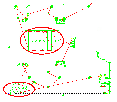
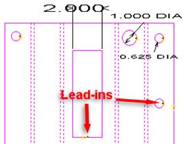
A view
of the part before Split Cut-outs
is enabled.
Notice that the Lead-ins are
visible
on each pattern. |
|
|
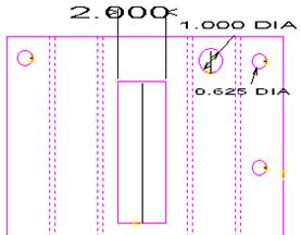
A view
of the same part after Split Cut-outs is enabled. The lead-ins
on two patterns have been lengthened according to user specifications.
Max
Width for
the cutouts was given as 2, so the two larger cutouts have been
included.
Min
Width was
specified as 0.7, so the smallest holes were ignored. |
|
|
|
|
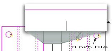
The close-up
here shows the lengthened lead-in and the gap created by the beam compensation,
which was set at 0.1. |
|
|
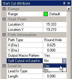
Enable
through Start Cut Attribute panel |
|
Users may also
enable this feature manually by going to Sequence
Features>Start/End Cut Attribute>Start Cut Attribute
and then selecting a pattern in the work area.
Individual
cutouts on separate patterns on a part or sheet can be switched
on or off here.
Changing
a Split Cutout through this panel does NOT automatically update
the settings in the Split Cutouts tab.
|
|
|
|
| |
|
|