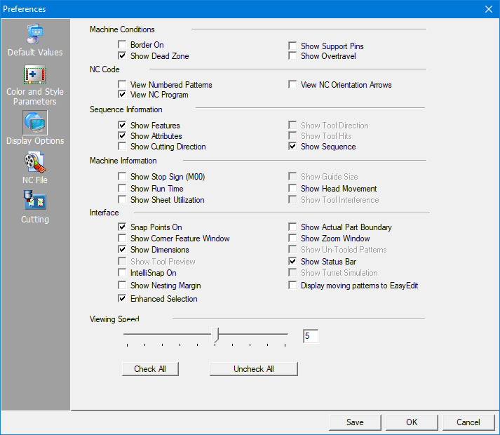
The options in the Display Options panel control the appearance of the elements during each redraw. If an option has a check mark, the feature is active; the element displays within the application window. If a check box is empty, that display feature is disabled; the element remains hidden unless requested by another View command.
Border On
<F3>
Border On controls the display of the part border. The <F3> key also controls the display of the part border in the work area. You may want to disable the display of the part border while you are designing the part, but view the part border during the sheet layout phase of your project. The part border color indicates whether it is currently selected, a copy of the selected part, a member of a grid, or the original part of a grid in the SHEET view.
Show Dead Zone
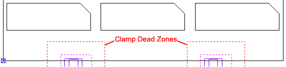
Show Dead Zone controls the display of the clamp dead zones. If enabled, the dead zones display. If disabled, the dead zones are hidden.
Note: An alert displays if a tool hit or cutting path enters a dead zone.
Show Support Pins
Enable Show Support Pins if you want to use and display the support pins for cutting systems.
When this option is on, the system will check for parts that may tilt and highlight such parts in red.
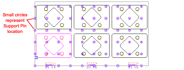
Click for info on enabling Support Pins and Configuring Support Pins.
Notes: Before you can display support pins, you must access the Info option on the Machine menu and define the support pins using the Place Support Pins feature.
To disable any unused support pins, use the Toggle Support Pins option on the Machine menu.
You must save any modifications with your default machine if you intend to use them for every sheet.
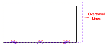
Show Overtravel
Show Overtravel displays overtravels as construction lines in SHEET View. Enable this option if you want to view the overtravels. Show Overtravel is only available for combination or cutting systems.
This option controls whether the part and the NC code includes pattern numbering. A number is assigned to each sequenced pattern, allowing you to reference patterns in your code to those in the work area.
Patterns are numbered from 1 to 999. If the number exceeds 999, the sequence is renumbered, starting with 1. If you enable this option, both the sequencing display and NC code will include a number for each pattern. The number appears in the code as a comment line before each pattern.Note: To be sure that the sequence numbers are visible in the work area, it may be necessary to select a darker color for the Tool Gouge/Cut Attr./Seq.# item.
See Color and Style Parameters>Set Color for more info.
View NC Program
If you enable this option, you can view the NC code after generating it. The Windows Notepad® application (or text editor of your choice) opens and displays the code. Make sure to save the code in the ASCII text format and not any other file format.
View NC Orientation Arrows
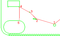
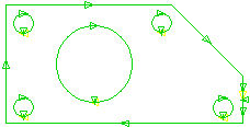
View NC Orientation Arrows enables the display of orientation or directional flags to indicate the NC coordinate origin. This allows you to determine the result of the code output. The following diagram illustrates how the coordinates display in SHEET View:
The NC coordinate origin may be started in the lower left-hand corner of the sheet (standard), the lower right-hand corner of the sheet, the upper left-hand corner of the sheet or the upper right-hand corner of the sheet.
Sequence Information display conditions consist of Show Features, Show Attributes, Show Cutting Direction, Show Tool Direction, Show Tool Hits and Show Sequence.
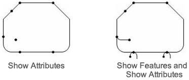
Show Features
To display cutting and punching features (such as microjoints, corner features, lead-ins, lead-outs, over/under cuts) after a redraw, enable the Show Features option.
Show Attributes
Attributes are cutting conditions applied to specific points along a path. The attributes appear as node pixels. The color of the node pixels is dependent on the range color used for the path. The Show Attributes option controls the display of the attributes after the work area redraws. If you enable the option, the attributes display as nodes along the cutting paths.
Note: Attribute features may display, but the cutting or punching path may not exactly follow the pattern(s) due to the interference checking performed by the system.
Show Cutting Direction
he cutting direction is the route the cutting head follows along a path. T You can display the cutting direction for sequenced patterns and those having start points. If you enable the option, the direction arrows display each time after the redraw. If you disable the option, the cutting direction displays only if you select the View Direction option from the Cut Sequence menu.
Show Tool Direction
Use Show Tool Direction if you want to see the punching direction with the tool hits and sequence. The direction arrows only display when SHEET View is active.
Show Tool Hits
Show Tool Hits controls the display of the tool hits when the work area redraws. This feature is useful when you are tooling a part and you need to enlarge or reduce the view.
Show Sequence
Show Sequence controls whether the sequencing displays after the work area redraws. This feature is useful when you are sequencing a sheet and need to enlarge or reduce the view of specific areas.
The Machine Information options consist of Show Stop Sign (M00), Show Run Time, Show Sheet Utilization, Show Guide Size, Show Head Movement and Show Tool Interference.
Show Stop Sign (M00)
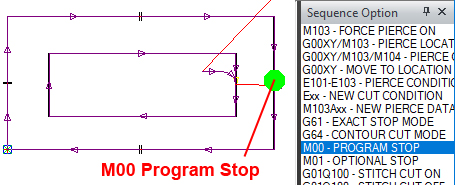
Use Show Stop Sign (M00) to view the program stop (or cycle stop) in the sequence. Your machine driver must support this option. To see the program stop, after sequencing it may be necessary to click on M00 - PROGRAM STOP in the Sequence Option panel.
Show Run Time
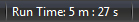
Use this option if you want the status bar to display the estimated run time when you view the sequence. Your machine driver must support this option. You must also enable the status bar display.
Run Time will not display if you're using a material that has no JK... (condition file) attached to it. You may open Sheet Info and select another material from the Material Group pull-down, or go to the Material Library and process the material according to the instructions given.
Show Sheet Utilization
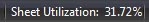
Use this option if you want the status bar to display the percentage of the sheet area occupied by parts.
Show Guide Size
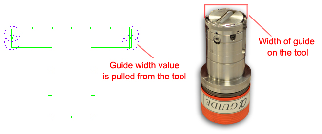
The Rectangle tools have guides assigned to them
Tool Guides allow the user to see if the tool placement is interfering with other tools or clamps. Check ON the Show Guide Size option to view the guide size for punching tools displayed with the sequence. Guide sizes for individual tools are defined in the Turret Information window. To enable guides for tools, see Creating and Editing Tool Stations.
Show Head Movement
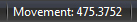
If you enable this option, the status bar displays the distance for the head movement when you view the sequence. You must also enable the display of the status bar.
Show Tool Interference
To have the program show interference between tools, check ON the Show Tool Interference option.
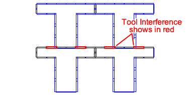
Note: The color used to hi-lite tool interference can be modified in the Preferences>Color & Style Parameters>Item Color panel.
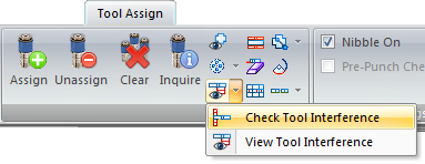
This option must also be enabled in the interface by using the Tool Interference options on the Tool Assign tab.
.
Interface display options affect your interaction with the CAD and CAM modes of the user interface. These options determine the display behavior of snap points, corner features, dimensions, tool hits and turret simulation.
Snap Points On
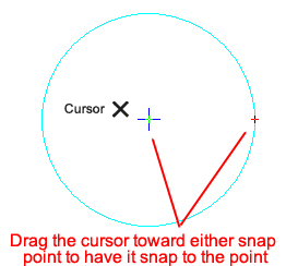
Snap Points On either activates or deactivates the display of the snap points. The Draw section covers snap mode and snap points in detail.
Show Corner Feature Window
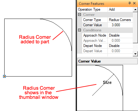
Enable this option if you want to display an enlarged view of a corner feature (loop, radius or tab) in the Corner Value window.
A Corner Feature may be placed on a part by using the Add Corner Feature option on the Sequence Features tab.
Show Dimensions
This option controls the display of dimensions when the work area redraws. Place a check mark in the check box if you want the dimensions to display each time the work area redraws. Use this feature when inspecting dimensions and closely examining part and sheet areas. See the Dimension tab for info on placing dimensions.
Show Tool Preview
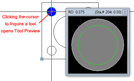
Place a check mark in the check box to have tool shapes and key angles display when a tool is inquired. See Inquire a tool for more info.
IntelliSnap On
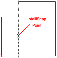
Place a check mark in the IntelliSnap On check box to have the system automatically enable the IntelliSnap feature for each AP100US system session.
See IntelliSnap for more info.
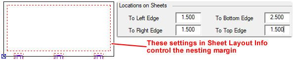
When this option is enabled, the user will see a dashed line representing the nesting margin, on the sheet in the Work Area. Place a checkmark in the checkbox to turn the option ON. Even when the option is disabled, the nesting margin will still be in place. Configure the Nesting Margin in Machine Settings>Sheet Layout Info>Location on Sheets.
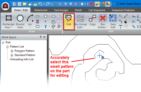
Check ON this option to make selecting precise patterns in a complicated part much easier. Use this option to Edit a pattern, Add a Pattern to a Cut Sequence or even Delete a pattern. Active in sheet mode and part mode. When this option is being used, Snap Points is automatically enabled in the background, regardless of the setting in the Display Options panel.
Show Actual Part Boundary
Actual part boundaries are the lines or arcs around the perimeter of a part. A rectangular part box displays to indicate the outermost points of the part (the part border). You can use the corners of this rectangle as reference points during sheet layout.
To view the actual part boundary, enable Show Actual Part Boundary. The actual part boundary displays, allowing you to use points on the boundary or within the patterns.
Note: On complex sheets consisting of intricate parts, you can display only the part border to decrease the redraw time. If you must accurately position a part using features inside the boundary or along an irregular edge, display the actual boundary. The option affects the Move, Copy and Rotate options on the Sheet menu.
Show Zoom Window
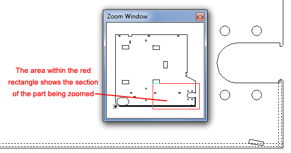
Check ON this option to control the display of the Zoom Window.
Show Un-Tooled Patterns
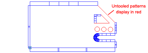
This option displays any un-tooled patterns display in the color selected in the Color and Style Parameters Pattern Without Tool color.
Show Status Bar
This option will toggle the display of the Status Bar along the bottom edge of the application window. Place a check mark in the check box if you want to display the Status Bar.

Remove the check mark to hide the Status Bar.
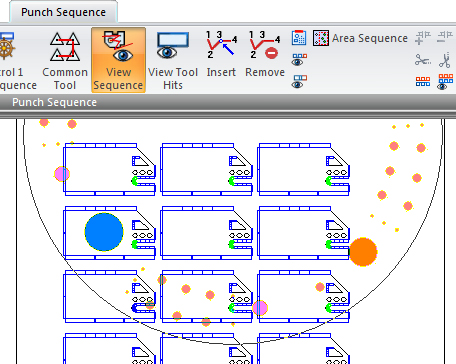
Show Turret Simulation
This option will toggle the display of the turret when you use the View Sequence option in Sheet View. If you place a check mark in the Show Turret Simulation check box, an outline of the turret will appear and trace the sequence. The graphic will also rotate to indicate which tool station is being used to process the sheet.
Display Moving Patterns to EasyEdit
Check this box to display the actual shape of the edited pattern(s) while they are being moved. If this box remains unchecked, the program only displays an empty rectangle when moving the pattern.
The EasyEdit feature makes editing patterns easier by allowing patterns to be edited with simple mouse-clicks. Pre-select certain editing functions (such as Copy, Move, Assign Tool, Add Microjoint and others) in the Customize dialog box and apply those functions directly to patterns in the work area.
(To enable and use EasyEdit, see Edit>Easy Edit.)
The Viewing Speed section and slider control allows you to specify the default viewing speed for the redraw of the cut and punch sequences, and for the tool hits in the work area. Select the slider and drag it to adjust the default viewing speed, or type a value in the field to the left. The range is from 1 to 9 for the viewing speed.
The user may also use the slider in the lower-right corner of the CADCAM work area.

Check / Uncheck All
Click the Check All button to select and enable all the options in the Display Options panel of the Preferences window.
Click the Uncheck All button to remove all the check marks from all of the check boxes. This will disable all the options in the Display Options panel of the Preferences window.