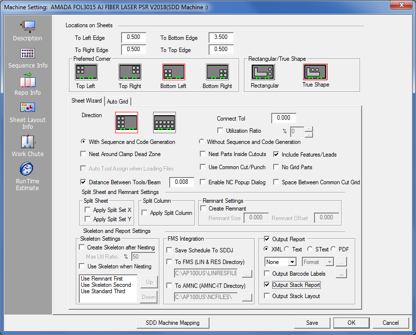
The Sheet Layout Info panel allows you to control the nesting layout. The Nesting Module uses the settings in this panel to nest parts. The options in this panel are disabled if your protection block does not support nesting.
Option |
Description |
|
Location on Sheets
|
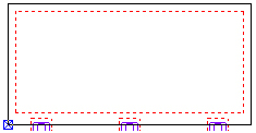
The fields in the Location on Sheets section allow you to specify borders around the edges of the sheet. Also specify the tolerance for gaps in part boundaries that the software should consider as connected.
|
|
To Left Edge |
This value is the minimum distance between the left edge of the sheet and the left edge of any nested part. |
|
To Right Edge |
This value is the minimum distance between the right edge of the sheet and the right edge of any nested part(s). |
|
To Bottom Edge |
This value is the minimum distance between the bottom edge of the sheet and the bottom edge of any nested part(s). |
|
To Top Edge |
This value is the minimum distance between the top edge of the sheet and the top edge of any nested part(s). |
|
Preferred Corner |
These options allow you to choose the quadrant of the sheet where you want nesting to begin. You can specify the upper left, upper right, lower left or lower right quadrants. The direction options determine whether nesting should be vertical or horizontal. Click the desired icon to choose the preferred corner. |
|
|
Click the Upper Left button to start nesting in the upper left sheet corner. |
|
|
Click the Upper Right button to start nesting in the upper right sheet corner. |
|
|
Click the Lower Left button to start nesting in the lower left sheet corner. |
|
|
Click the Lower Right button to start nesting in the lower right sheet corner. |
|
|
|
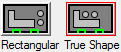
If Rectangular is chosen, the program will not allow nesting inside the perimeter notch in a larger part’s profile. When True Shape is selected, the program will allow such nesting. The selection made here will become the global setting in Sheet Wizard. The same setting found in the Sheet Wizard Layout Setting section is synchronized with this setting. |
Option |
Description |
Direction |
Click the desired icon to choose the preferred nesting direction. |
|
Click the Y-Axis button if you want to system to fill the sheet vertically. |
|
Click the X-Axis button if you want the system to fill the sheet horizontally. |
Connect Tol |
The connection tolerance is the maximum size of a break in a part boundary. The system compares the size of the break to the connection tolerance. If it is less than the connection tolerance, the system can nest the part. If the break is larger than the connection tolerance, the system prompts you to repair the open part boundary. |
Utilization Ratio |
The Utilization Ratio option allows you to enable sheet utilization and specify what percentage of utilization of the sheet is to be used to nest a given job. If you enable this option, the nesting software will only generate sheets that fill the utilization ratio. The default value of 70 appears in the Use Ratio scroll box. You can click the up and down scroll arrows to toggle through the utilization ratios in 5 percent increments. The range is 0% to 100% utilization. |
Nesting Preferences The following options provide you with greater control over the nesting process. |
|
With Sequence and Code Generation |
Select this option if you only want to create a nest containing sequencing and generate NC code or NC programs. This option is synchronized with the same option in Sheet Wizard>Settings>Sequence Settings panel. |
Without Sequence and Code Generation |
Select this option if you only want to create a nest job without sequencing and without any code generation. This option is synchronized with the same option in Sheet Wizard>Settings>Sequence Settings panel. |
Nest Around Clamp Dead Zone |
A check mark in this check box instructs the system to nest parts around the dead zones reserved for the sheet clamps. |
Nest Parts Inside Cutouts |
A check mark in this check box instructs the system to attempt the nesting of parts within the holes or cutouts in other larger parts as space allows. |
Include Features/Leads |
This option instructs the system to evaluate the values of the part features (corner features, lead-in lines, lead-out lines, etc.) while attempting to nest the parts. If you remove the check mark, the system ignores the part features while nesting and only uses the value you have specified for the Distance Between Tools/Beam option. |
Auto Tool Assign when Loading Files |
Use this option to determine whether the system automatically assigns tools when loading files for a nest job. Place a check mark in the check box to automatically assign tools during the nest job. |
Use Common Cut/Punch |
Enable this option to allow a per-part common line cut and punch function, which will effect all kinds of machines, including punch, cutting and combination. When checked, save the setting by clicking Save to make this the default setting. |
No Grid Parts |
This option allows you to instruct the system whether to process gridded parts as a single unit, or to ignore gridding and individually process the patterns as single parts, rather than a collection of parts. |
Distance Between Tools/Beam |
This option allows you to specify a value for the spacing of parts from beam width to beam width. |
Enable NC Popup Dialog |
When the program outputs NC code various prompts will be hidden. Check the box to allow all prompts to display. This will require the user to manually respond to each prompt. Note: This checkbox calls the same function as in the Sheet Wizard>Settings. Consequently, when this checkbox is toggled ON/OFF, the function will likewise be toggled ON/OFF in the Sheet Wizard. |
Space Between Common Cut Grid |
Check the box to enable a space to be placed between grids during the common cut process. The space is the value from the Distance Between Tools/Beam field. |
Split Sheet and Remnant Settings Use the options in this section to define your split sheet settings and the creation of remnants and their sizes. |
|
Split Sheet |
Place a check mark either or both of the check boxes if you want the system to cut the sheet into smaller sections for easier handling when unloading. The “splitting” occurs during nesting. These options apply to the Sheet Wizard. |
Split Column |
Place a check mark in this check box if you want the system to split the columns after nesting. This option applies to the Sheet Wizard module. |
Remnant Settings |
Place a check mark in this check box to allow the system to create a sheet remnant when nesting parts. Enter a minimum Remnant Size and Remnant Offset values. If the portion of the sheet available for a remnant is larger than the Remnant Size value, the system will cut a remnant. If it is smaller no remnant will be cut. Both Remnant Settings and Skeleton Settings can be enabled and will function together. The system will consider Remnant Settings first and if a remnant cannot be cut it will default to Skeleton Settings. The remnant is added to the Material Inventory and stored in the Material Library. If this option is not enabled, the system nests parts to previously defined edge settings. Notes:
Remnant settings also take effect for Straight Common Cutting. |
|
Use the options in this section to define your skeleton settings and to specify which format the Sheet Wizard module is to use for reports. |
|
Skeleton Settings |
|
Create Skeleton after Nesting |
Select this option to allow the system to create skeleton sheets after a nest job is completed. The skeleton sheet is added to the Material Inventory and stored in the Material Library. When this option is checked ON, the Max Utl Ratio field will become active and the percentage value is editable. If the value is set to 50%, and actual sheet usage is greater than that value, no skeleton will be created. If sheet usage is less than the value a skeleton will be created that can be reused later. Both
Skeleton Settings and Remnant
Settings can be enabled and will function together. |
Use Skeleton when Nesting |
Select this option to allow the program to include existing skeleton sheets in a job during nesting. |
Use Remnant / Skeleton / Standard |
Prioritize sheet usage by selecting a sheet type and moving it up or down in the priority list. If a high-priority sheet type is not available in the Material Library, the program will automatically skip to the next type in the list. |
|
|
Save Schedule to SDDJ |
Activate the check box to save the Schedule output from Sheet Wizard to an SDDJ server that was selected during the AP100US installation/update. If an SDDJ server was not selected during product installation, or the SDDJ server does not exist, the user may still save the schedule to a file. See also SDD Machine Download for more info. Contact Sales Support to learn how to activate the SDDJ Server. |
To FMS (LIN & RES Directory) |
Place a check in the check box to activate the text box. Type in a directory or click the Browse Button to navigate to the folder where you want to put the LIN and RES file for FMS Integration. |
To AMNC (AMNC-IT Directory) |
To generate a .LI1 file (compatible with AMNC-IT) check ON the box. The program will send the file to the default folder indicated. If needed browse to another directory. |
The user has the option of generating or not generating reports and their related files. To NOT generate reports (while still generating NC code) uncheck the box. When this is done, the user may still make changes to the options in this section. |
|
XML |
If you select this option, the nesting program creates a nesting report using the XML (Extensible Markup Language) standard. XML is the default. |
Text |
If you select this option, the nesting program creates a nesting report using the ASCII text format. The report consists of ASCII text only. |
S Text |
If you select this option, the nesting program creates a nesting report using the S Text format. |
If you select this option, the nesting program creates a nesting report using the PDF format defined. |
|
None (drop down list) |
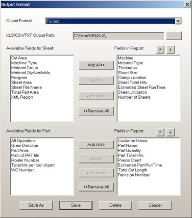
Leave the pull-down menu at None or choose XLS, CSV or TXT. When a choice is made the button becomes active. Click it to open the Output Format dialog shown here -
To add or remove fields that will appear in the output document, select a field and then click the Add or Remove button.
|
Format (drop down list) |
Choose a pre-defined format from the options listed.
|
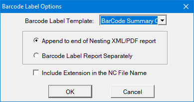
Check the box to allow Barcode labels to be printed. Click the button to open the Barcode Label Options dialog shown here -
Select a Barcode Template from the list. The nesting module can either attach a barcode label to the end of the printed report (choose the Append radio button), or print out a barcode label by itself (Print option). Check ON the checkbox to include the Extension in the NC File Name. |
|
Output Stack Report |
Check ON the option to include part stacking info in the report. Part Stacking files must be made available by using the Part Stacker Module and generating required files. See Part Stacker Module. |
Output Stack Layout |
To include the actual stack layout in a report, Output Stack Report and this option must both be checked ON. |
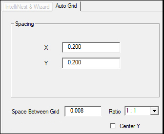
Note: The settings here are also found in the Sheet>Sheet Options>Auto Grid Panel. Settings in both panels are synchronized.
Option |
Description |
Spacing X / Y |
Enter values into these fields to specify the horizontal and vertical grid spacing between the parts in a grid. |
Space Between Grid |
Enter a value to control spacing between grids. |
Ratio |
Choose either 1:1 or 1:2 (large parts to small parts) to confirm the amount of parts that will be auto-added to the sheet. This ratio is called when Method D is selected in the Sheet Wizard>Settings>Sheet Layout Info section. |
Center Y |
Check ON this checkbox to allow grids to be centered in the Y. |
|
|
Clicking this button links the current machine in AP100US to a Machine registered in SDDJ. Data from the programs that have been stored into SDDJ can be linked to other products that link to SDDJ (such as AP100G CAM or Dr.ABE_Blank). Contact Sales Support to learn how to activate the SDDJ Server. Click for complete SDD information. |
|
Save / OK
|
Click Save to make these the default settings for AP100US. Selecting OK uses recently entered settings for this session only. |
Cancel |
Closes the window without saving any new changes. |