| Add (Load) Parts | Assembly Panel | |
| Batch Convert | Select Part from Part List | |
| Open XLS/CSV/TXT | Load Parts from SDDJ | |
| Save XLS/CSV/TXT |
![]() When the Sheet Wizard main interface first opens, the Add (Load) Parts
panel is already displayed. If the program shows another panel such as
Machine or Settings, click on the Load Parts button to display Load Parts.
When the Sheet Wizard main interface first opens, the Add (Load) Parts
panel is already displayed. If the program shows another panel such as
Machine or Settings, click on the Load Parts button to display Load Parts.
Above the Layout Setting panel is a row of buttons that control loading. Click Add to begin loading parts from the C:\AP100US\PARTS installed folder. (Click for info on loading parts from XLS/CSV/TXT files and parts from the SDDJ server.)

Remove will delete a highlighted part from the list. Clear All will remove all parts from the list. When Add is clicked the Open File window appears -

Add parts individually by double-clicking a part, or multi-selecting parts. If necessary browse to any other folder where parts are stored to select. When parts are selected, click open to load the parts into Sheet Wizard.
The Sheet Wizard supports GRP/IGA/IGS and DXF (with multiple boundaries) files.
Part Groups or Kits may also be loaded into the Sheet Wizard Parts List. Click on the Group (*.grp) option in the Files of type: pull-down to open the GROUP folder. Click for more info on Part Groups and Kits.
Click the Find button to filter parts to load into the Sheet Wizard. Part Groups or Kits do not have this filter. Parts may also be Batch loaded. Click for complete info on the Open File window.
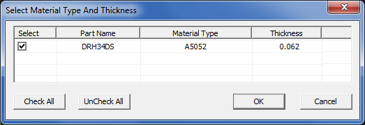
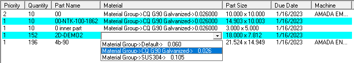
Material Type & Thickness
Check
If the user attempts to open a part that was saved with a material type
that differs from the material currently loaded for the current sheet,
the Select Material Type and Thickness
dialog will automatically open.
Checking ON a material type will force that part to use the selected material for the current job. If the part remains unchecked it will not be allowed into the current nest.

Use this option to batch convert DXF and DWG files to AP100US-compatible .PRT files, which can be loaded immediately into the Sheet Wizard. Batch Convert will open a 3-view ortho drawing, grab the flat part and load it into Sheet Wizard.

Browse to "From" and "To" directories and click Convert. Click Show In List to have the newly converted files added to the Parts List for Nesting. Click Check Date to see when files were modified in the past and View Log for conversion info in a txt file.
Note: The Batch Convert button by default is disabled. To enable the button see Settings>Advanced Settings>Other Settings.
Batch
Convert Settings
To choose naming conventions and/or create a sub-folder for the converted
prt file open the Settings dialog.
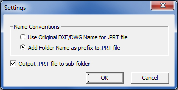
Stay with the original name or select Add Folder Name as prefix to .PRT file, which will place the folder name (such as "converted parts") to the beginning of the original prt name.
Check ON the Output .PRT file to sub-folder to have the system create a subfolder for the converted prt file.

To open the Assemblies folder hit the Open XLS/CSV/TXT button.
This option allows the user to import CSV and TXT files (from AP100US or MRP/ERP software, for example). Click the button to open the file, which defaults to the C:\AP100US\ASSEMBLIES folder show below. Browse to any other folder as needed.
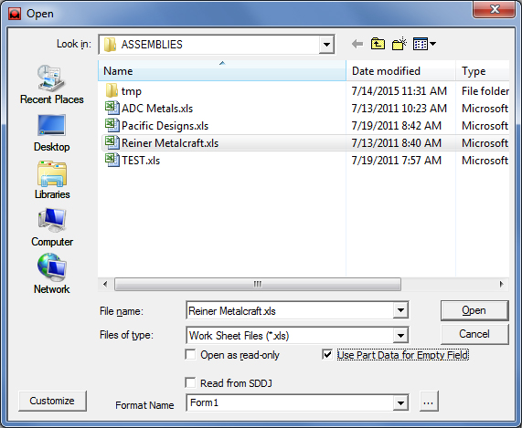
Highlight a file and click Open to open the file in the Part List for Nest pane of the Schedule Panel.
The Files of type drop-down defaults to .xls, but .cvs or .txt files can be selected as needed.
Check ON the Open as read-only box, if the file to be opened should be protected against unintended editing.
Check ON the Use Part Data for Empty Field to allow the program to use data saved with the part file to populate empty fields in the program interface.
Checking ON Read from SDDJ allows the program to pull part data from the SDDJ server.
Note: The format that the file is saved with will appear in the Format Name field for any highlighted file.
If a file does not have a Format Name already, the Format field will be empty, and the system will
prompt the user to select a format. However, even if a format is selected here, the file still may not open.
Read Save XLS/CSV/TXT below for more info on how to save an imported file with a format.

Click Customize to open the CAD file Loading Options window shown here -
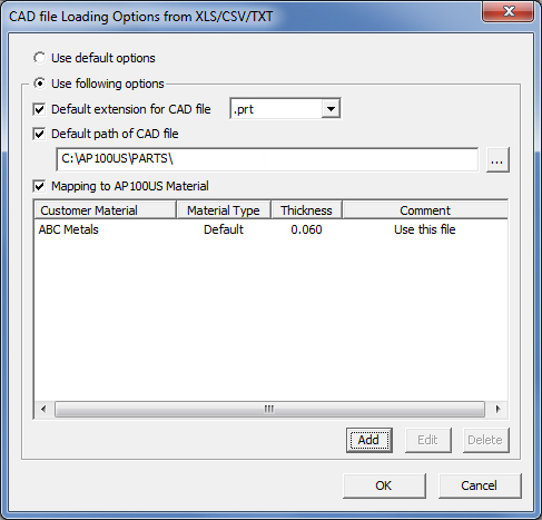
If there is no extension on a part name, a corrupt path or other issues that interfere with part loading, this window gives the user various choices that can assist to load a part.
Select Use following option to activate these choices -
If there is no part extension, check the Default extension for CAD file box to assign an extension from the pull-down list.
Use Default path of CAD file to define the part folder that will be loaded in the program through the XLS/CSV/TXT file.
Use the Mapping to AP100US Material to map the material to AP100US material. Click Add to enter a material. When a material has been added, the Edit and Cancel buttons become active.
Click OK to keep the file loading options, or Cancel to cancel the operation and delete and user input.
Review Settings
To review current XLS settings before selecting a file to load, highlight the file in the Open pane, and then click the settings button to open the Option window shown here -
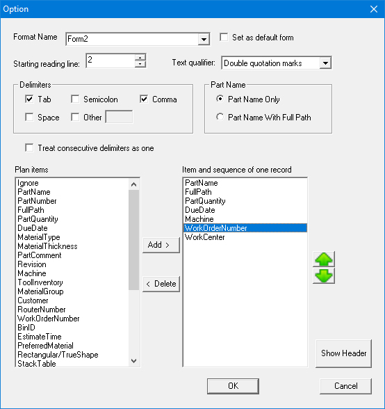
It is possible to create and save a new Format Name here in the Option window, and even edit the Items lists; however, such changes cannot be applied to an imported file. When making changes that must be applied to a file, it's necessary to make them in the Save XLS/CSV/TXT dialog.
Read Save XLS/CSV/TXT below for more info on creating new Format Names, editing and saving imported files.
Show Header
Toggle the Show Header button to display/hide the User Header Items
dialog. This read-only dialog shows the header contents and correct order
of the items from the file format that they are setting up.
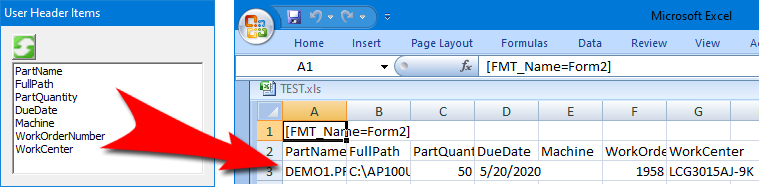
Plan items as they appear as column headers
in an xls file
When Selecting a different Start reading line, refresh the view in User
Header Items by clicking the green refresh button.
If Start reading line 1 is selected, the Form Name will display.
Line 2 shows the entire list of Plan items saved with the file (as shown in the above image).
Lines 3 and following show information for parts in the file.

Click to save edited XLS, CSV and TXT files to the Assemblies folder (or to any desired directory). Select the file or files in the Part List that will be edited and saved (this action also activates the Save XLS/CSV/TXT button). Select the same file or files in the Save As window.
Note: If one file is selected in the Part List, and a different file is selected for editing in the Save As window, then these files will be merged along with any new changes when saved.
When the button is clicked, this Save As dialog will appear -
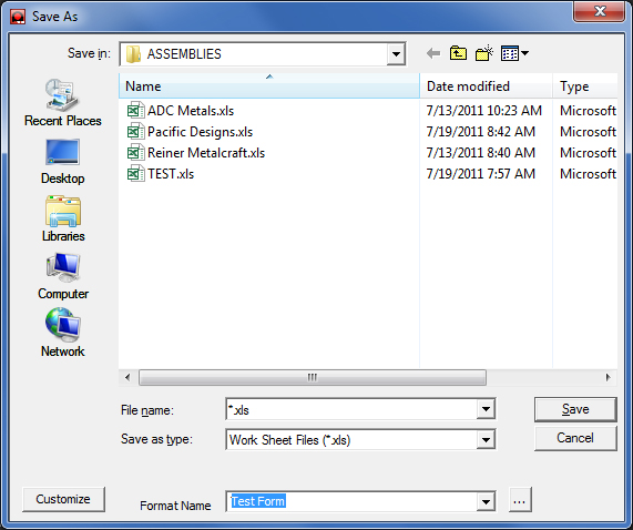
Select a file to edit (or select a file type from the Save as type drop-down if needed).
In the Format field, select the format type to save with the file, and then click Save. Assign a new name to the file, or overwrite the current file. Any other changes must be done in the Option window.
To edit and save other XLS file settings, click the settings button to open the Option dialog shown here. Be sure that the file to be edited is highlighted in the Save As pane before clicking.
Notice that the read-only Show Header option is absent here
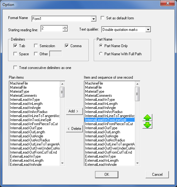
Format Name
A Format Name in an XLS file decides which Plan items to use as column
headers in the file itself and in which order they will appear.
Select one of the existing Formats available in this drop-down, or create a new Format Name by entering a unique name in the field, and then building an Item and sequence of one record list by adding items from the Plan Items list, and then adjusting their order as desired.
Note: A new format name may be created and saved by clicking OK. However, to insert the new format name (or any changes) into an XLS file requires that the Save button in the Save As dialog be clicked.
Set as default form
Checking this option ON will make the current form in the Format Name field
the default. Even with a default form selected, the user may still select
other forms available on the pull-down menu.
Start Reading Line
Select which line the program will begin reading the .xls, .cvs or .txt
file on. The program defaults to line 2 here, as that line typically displays
the column headers. Keep that setting or select another.
Text Qualifier
This option allows the user to select the punctuation marks used to qualify
items. Choices available are “Double quotation marks”, “Single quotation
marks” and “none”.
Note: This option only applies to TXT files.
Delimiters
Delimiters are used to separate string formats into unique data entries.
For example, the string Demo; 15; 2011-11-16 uses semicolons to
divide unique values/entries.
Available delimiters are Tab, Semicolon, Comma, Space and Other (user-specified).
Note: This option only applies to TXT files.
Part Name
Part Name Only
Allows the user to specify that the file's PartName data column will contain the Part Name only.
Part Name with Full Path
Allows the user to specify that the file's PartName data column will contain the Part Name in addition to the part's full path.
The full path will use the Import files Directory to pull the Part into the Schedule list. If the Full Path does not exist in the Import file, then the default path within the Win.ini will be used to pull the part into the schedule
Treat consecutive delimiters
as one
If more than one of a certain delimiter type is entered in a row, checking
this box allows the program to treat them as one delimiter.
Plan Items
These are available plan items (column information headers) that can be
stored in an xls file. Select items to appear in the record by highlighting
an item, and then clicking Add to insert the item into the list
on the right (multiple-selection is supported).
Notes:
Plan items selected here are used by are used by other systems’ ERP or MRP information.
Part Name is mandatory and can’t be deleted; without it XLS/CSV/TXT files can’t be imported.
Item and sequence of one
record
Selected items from the Plan items list appear here. Delete unwanted entries
by highlighting, and then clicking Delete.
Note: It's best to have at least three or four items in the record.
The order (top to bottom) of the items shown in this pane, will appear from left to right in the saved xls file. Highlight an item and then click the green up/down buttons to move it to the desired order in the list.
OK / Cancel
Click OK to save changes in the option panel. To save the changes
to a file, click OK here and then Save in the Save As window.
Click Cancel to close the dialog without saving.
Assembly
Panel
Using the Sheet Wizard Assembly option the user may define and manage a
group of parts as an assembly (ext: *.asy), load the assembly into the
Sheet Wizard Parts List for Nesting and process in the usual manner.
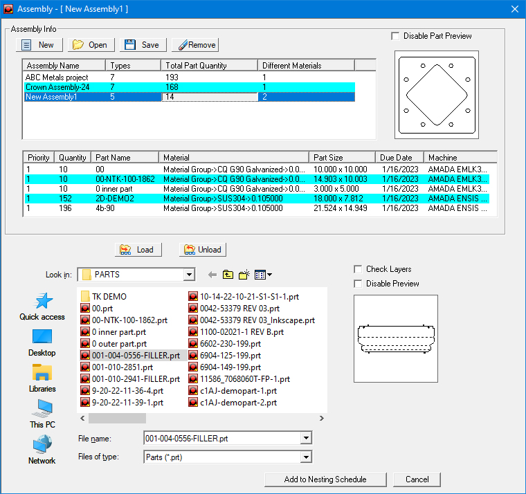
Assembly Info
New
Select this option to create a new assembly (*.asy) file. When you
select New, the system will add a default assembly name of “NewAssembly1”,
“NewAssembly2”,etc., to the Assembly Information table. Update an assembly name by clicking
on and entering text directly into the cell.
Open
Use
to load an existing assembly file. The Open File dialog box will list
all the previously saved assembly files stored in the C:\AP100US\ASSEMBLIES
folder. Select a file (or multi-select more than one) and then click Open
to load the assembly.
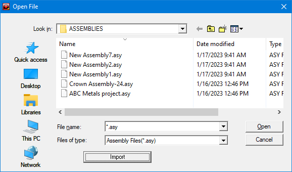
With
the Import button import
data from xls, txt and csv file formats. See
info below.
Save
Select to save a new assembly or any changes made to an existing assembly.
Select a file name (or multi-select more than one) and click to save to
the C:\AP100US\ASSEMBLIES folder.
Remove
This option will remove a selected assembly (or assemblies) and the parts
associated with it from the tables in the Assembly panel. This only removes
the record from the table; it does not erase the assembly file or part
files from the hard drive.
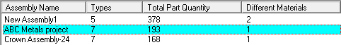
Assembly Information Table
The Types, Total Part Quantity and Different Materials
columns contain read-only info that is carried over from the Part Info
Table.
Assembly
Name
This
field displays the name of a new assembly or the assembly currently loaded
into the system using the Open option. Rename a file by selecting the
text and editing directly in the field.
Types
This field displays the number of distinct parts the system has found in
the entire assembly.
Total
Part
Quantity
This field displays the sum total of all the quantities of the parts belonging
to the assembly.
Different
Materials
This field displays the number of different types of materials that are
used in the assembly.
Part
Information Table
This table shows parts that have been loaded into the Assembly file that
is selected in the Assembly Information Table shown at the top of this
page.
Double-click any tool/row
to open the Part Info panel to edit part attributes (shown
below)
Priority
The priority assigned to the part. Click the field to type in a new value,
click twice to activate the drop-down list and select a priority for the
part, or double-click to edit in the Part Info dialog.
Quantity
The quantity of this unique part. Click twice to select the current contents
and type a new quantity for the part or double-click to edit in the Part
Info dialog.
Part
Name
The name of the part; double-click to edit in the Part Info dialog.
Material
The material assigned to the part. Click twice to activate the drop-down
list and select a material for the part or double-click to edit in the
Part Info dialog.
Part
Size
This field displays the overall part dimensions. This field is static;
the contents cannot be edited.
Due
Date
The date the part is due for production. Click twice to activate the drop-down
list and select a new date from the Calendar or double-click to edit in
the Part Info dialog.
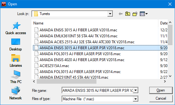
Machine
The machine assigned to process the part. Click twice then click the button
to open the Turret dialog (shown below) and select a machine, or double-click
to edit in the Part Info dialog.
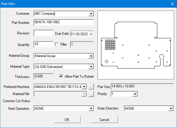
Part
Info Panel
Edit part attributes
such as Customer, Quantity, Due Date and Material in this panel.
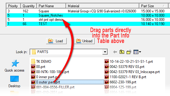
Load
/ Unload Parts
Use the Load option to load parts
into the assembly that is selected in the Assembly Information table.
Select a part or parts from the open Parts folder and then hit the Load
button, or simply drag the parts to the Part Information Table.
Add
to Nesting Schedule
Click
Add to Nesting Schedule when the assembly selected in the Assembly
Information Table is ready to transfer to the Parts List for Nesting
in the Sheet Wizard interface.
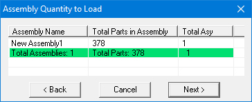
When
the Assembly Quantity to Load dialog opens, edit the value in the
Total Asy cell as needed and then click Next > to load
the assembly into the Sheet Wizard, or click < Back to return
to the Assembly panel. Selecting Cancel closes the Assembly panel.
Importing Assembly Information
The
Import option in the Open File dialog allows data from Microsoft
Excel (*.xls), Text (*.txt) and Comma Separated Value (*.csv) file formats
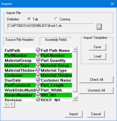
to be imported. The Import window will appear when you select Import
in the Open File window.
Import
Window
The
options in the Import window allow you to parse the information in delimited
(tab or comma) Text, Excel or CSV files.
Import Window Options
Option |
Description |
|
Import File |
This section allows you to select the delimiter type and the import file. |
|
Delimiter Tab |
Select Tab after Delimiter if the fields are separated by tabs in the import file. |
|
Comma |
Select Comma after Delimiter if commas are used to separate the fields in the import file. |
|
Path
and
|
|
This field displays the path and file name of the import file. You can click the navigation button to the right and select the Text File (*.txt), Excel File (*.xls) or Csv (*.csv) file that you want to import from the Open dialog box. |
Source File Headers |
The labels that appear in this column are the actual field headings that were found in the import file by the system. |
|
Assembly Fields |
The labels that appear in this column are the field labels of the nesting schedule assembly database. |
|
Import Templates |
Use the options in this section to create and save import templates. Import templates allow you to save the parameters you defined for parsing the import data for later use. Import templates are stored in the \Assemblies folder by default and have the filename extension of *.Templ. |
Save |
Click Save after you have defined the parsing parameters for importing data. A standard Save As dialog box will appear. Type a name for the template file in the File name: text box and then click the Save button. |
Load |
Click Load to load a previously saved import template file. You must first choose a Delimiter type (Tab or Comma) and load the data file before you can load the template. A standard Open dialog box will appear after you click Load. Select the desired template (*.Templ) file and then click the Open button. |
Check All |
Click to mark all the fields for importation. Check marks will appear in all the Field Selection buttons. |
Uncheck All |
Click to remove the import flags from all the fields. See Field Selection buttons. |
Import |
Click the Import button in the lower right-hand corner of the Import window to import the data in the source file into the assembly database. |
Cancel |
Click Cancel to exit the Import window without importing. |
Assembly Database Fields
It is important to understand the basic structure of the assembly database. The data contained in the import file into the corresponding fields of the assembly database must be parsed. The structure of the assembly database is as follows: |
|
Field |
Description |
File Name |
The full directory path and file name of the part. For example, C:\AP100US\PARTS\Part0001.prt. The path and file name must be included in the import file. The system will display an error message if the path or file name is incorrect. The system uses this information to locate the actual part on the local drive or network that will be included in the assembly. |
Part Name |
The actual part name that will display in the Part Name + Path field of the Part Information Table. |
Part Quantity |
The part quantity. The quantity value must be greater than zero. |
Material Group |
The material group associated with the part. The material group name must match that of a group name in the Material Inventory. |
Material Type |
The material type associated with the part. The material type name must match that of a material type in the Material Inventory. |
Customer Name |
The customer name associated with the part. |
Part_Length |
The length of the part. The system will correct this value automatically if the specified length in the import file is different from that of the actual size of the part file. |
Part_Width |
The width of the part. The system will correct this value automatically if the specified width in the import file is different from that of the actual size of the part file. |
WO_NO |
The Work Order number assigned to the part. |
ROUT_NO |
The Router Number assigned to the part. |
Field Selection Buttons
|
||||
|
Field Order Arrows
|
||||
|
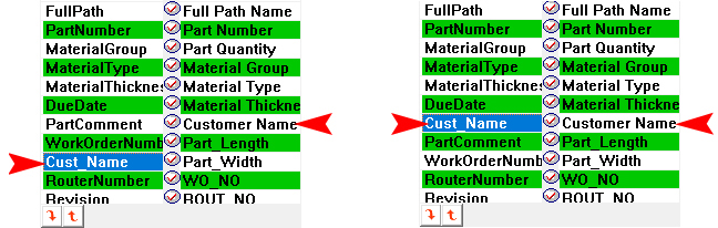
Parsing the Data
In the example below, the data in the Cust_Name field that the system found in the source file corresponds to the Customer Name field in the nesting assembly database. However, the Cust_Name field is in the wrong order. The system would display an error message if you were to attempt to transfer the data, even though it might be valid, into the wrong database field of the assembly database. |
|
To correct the order, you would click the Cust_Name field in the Source File Headers column to select it and then click the up and down Field Order buttons until Cust_Name field occupies the same order as that of the Customer Name field in the assembly database: |
Note: You can also click and drag the field labels in the Source File Headers column to the desired position. The <Shift> and <Control> keys can be used to select and move multiple field labels to the correct order. |

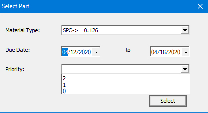
Search for a certain part in a long list of parts by clicking the Select button and entering filter parameters. Search by Material Type, Due Date or Priority, hit Select and that part will be highlighted and moved to the top of the Parts List.
Click to load parts from the SDDJ server. Browse to the necessary server and then select Data Type. Click Open to open the selected part(s) in the Sheet Wizard Parts List.
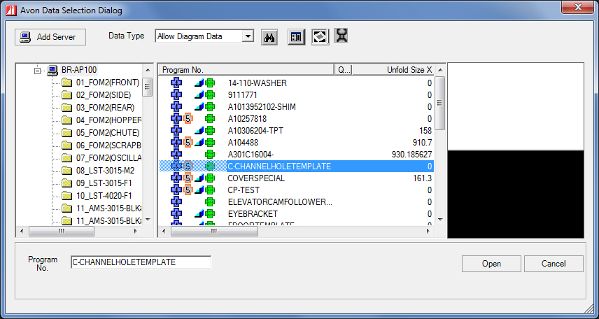
The Load Parts from SDDJ button appears only when the user has SDDJ client installed