Sheet Wizard
Sheet Wizard allows the user to select many different parts for nesting, and multiple sheets with different nesting patterns can be generated. Click the Sheet Wizard icon on the Modules menu to launch Sheet Wizard.
Note: AP100US can be started in the Sheet Wizard mode if the user selected the Sheet Wizard Mode option during a new installation of the software, or if the Sheet Wizard Mode option in the Preferences > Color and Style Parameters window has been checked.
| Control Buttons | Job List, Machine, Tooling & Materials | Parts List for Nesting Columns | Function Buttons Row |
| Flyout Menu | Layout Settings | Nesting Parameters |

Sheet Wizard control buttons
![]() When the Sheet Wizard first opens the Load Parts panel is active, with
the button highlighted in yellow as in the image on the left. Click the
Add button to browse to the local
directory and select parts. See more info on Adding
/ Loading parts.
When the Sheet Wizard first opens the Load Parts panel is active, with
the button highlighted in yellow as in the image on the left. Click the
Add button to browse to the local
directory and select parts. See more info on Adding
/ Loading parts.
Note: It's best to enter Layout Settings (such as Material Type, etc.) BEFORE parts are added to the Parts List. This will force most added parts to acquire the desired config settings.
The Schedule List, Edit Layout, Machine and Settings buttons are also available in this area. The Start Nesting button, which starts the nesting process, is only selected after a job in the Sheet Wizard has been properly configured.
Job List, Parts List, Machine, Tooling and Materials Selections

With a Combo mac loaded,
the currently loaded Machine name, Tool Inventory and Material are seen
If a laser mac is loaded, the Tool Inventory field will be empty
Click the Job List button to open a window listing archived jobs. See Job List on the Start Nesting page for full info.
The Parts List is the default view in Sheet Wizard. It shows parts that have been added to the Parts List by clicking the Add button.
Parts List for Nesting Columns
In the Parts List, Move
columns left or right by dragging the column header to a new location.
Resize columns by dragging the The parts list supports multiple-selection. Choose <ctrl> + click or <shift> + click to select more than one part to make changes. Right-click a column header to open the Column View flyout menu shown here. Toggle columns ON/OFF as needed. Part File Name, Part Size, Customer, Material Type, Quantity and Thickness display by default and cannot be switched OFF. Certain headers can be edited by clicking in the column cell and making a selection from the pull-down menu and/or entering text. Note: Some options (ex: Stack Table & Pallet/Bin ID) are driver-dependent and don't appear for all machines.
|
Right-click any column header to display the flyout menu for Columns |
Option |
Description |
Status |
Symbols in the Status column show the condition of a part -
If a part in the Parts List gets "kicked out" (due to a shortage of material for instance) its info will display in red. (See View>Error Location Sparks and Edit>Process Geometry for more information on correcting part gaps.) Note: The Status column is read-only. |
Part File Name |
Displays the name given to the part when it was created. This information is read from the part file. Note: The Part File Name column is read-only. |
Part Size |
Displays the size of the part. This information is read from the part file. Parts are listed based on the rectangular boundary area of the part, NOT the first dimension. Note: The Part Size column is read-only. |
Customer |
Displays the name of the customer. This information is read from the part file. Note: The Customer column is read-only. |
Displays the type of material. This information is read from the part file. Double-click to activate the pull-down menu, which lists all the material types in the Material Library for the current material group. Nesting
Multiple Materials |
Quantity |
If more than one copy of a part will be used in the project, double-click in the Quantity column, manually enter the new quantity and click OK to update.
Note: The program automatically decides if multiple copies of a part will be assigned to different sheets. |
Rotation |
Choosing Yes allows the program to rotate the part as needed, insuring a better fit between parts when nesting. Highlight and then click again on this column to display the drop-down list. Choose Yes or No (disable rotation).
Entering < y > or < n > on the keyboard will toggle Rotation and No Rotation. Notes: Rotation is NOT available for parts
loaded from a part kit (or group). |
Common Cutting |
By default all parts load with No in the Common Cutting column. Highlight and then click again on this column to display the drop-down list. Choose Yes (enable Common Cutting) or No. Entering < y > or < n > on the keyboard will toggle Common Cutting and No Common Cutting. Note: This option may be switched ON permanently in the NestWizard.ini file in the Parm folder in the AP100US installed folder. Additional Notes: Common Cutting parts must share the same
tool and boundary. |
Grain Direction |
Highlight and then click again on this column to display the drop-down list. Choose None, Horizontal or Vertical to set grain direction. Entering <h>, <v> or <n> on the keyboard will toggle Horizontal, Vertical and None. Note: Grain Direction info comes from selections made in Material Library. Note: Grain Direction options may be switched ON permanently ("0" = None, "1" = Horizontal, "2" = Vertical) in the NestWizard.ini file in the Parm folder in the AP100US installed folder. |
Revision |
Displays the revision number or letter that was entered when the part was last revised. (See Part Info>CAD Information for more details.) Note: The Revision column is read-only. |
Group Name |
This column contains information only if a Part Group or Part Kit has been loaded into the Tool List. Note: Part Groups and Kits will be processed by the Sheet Wizard in the same way as they were arranged in AP100US. Click for more info on Part Groups and Kits. |
Rectangular/True Shape |
If Rectangular is chosen, the program will not allow nesting inside the cutout of another part’s profile. When True Shape is selected, the program will allow such nesting. Selections made here apply to individual parts and will override the global setting in the Sheet Wizard Layout Setting section covered on this page and in the Machine Settings > Sheet Layout Info panel. |
Sheet X/Y |
Sheet X
and Sheet Y pull the sheet size value from the Layout
Setting>Sheet Size pull-down. When these columns are active
the Quantity will automatically
show the number of parts that can be nested on a single sheet.
Changes are allowed by entering new values directly into the cell.
|
Stack Table |
Assign stacking tables to specific parts by entering the number of a stack table in the cell. This driver-dependent option works with PSR and TK machines. When using a TK machine with Conveyor option, enter <1> to have the parts unload to the stack table, or enter <2> to have the parts unload to the conveyor. To use this option the Machine Setting>Sequence Info>Auto Unload checkbox must be switched ON and NC code must be generated. (Be sure With Sequence and Code Generation is selected in Sheet Wizard>Settings>Sequence Settings.) |
WO Number |
The user may double-click to activate the cell and enter a Work Order number if needed. If the user has FabriTRAK installed, this column will display the work order number assigned to the job in the FabriTRAK system. |
Router No |
User-assigned number identifying the "route" the part will take; that is, the part will start at a laser station, then be passed to a bending or painting station. |
Part Number |
Double-click a part number to open it in the AP100US work area for editing. See Editing a Part in the Parts List below. The number (name) of the part itself is read-only. |
Due Date |
Assign a Due Date by clicking in the cell to assign today's date. Double-click again to display flyout calendar and select a date. After a date is assigned to one part, all additional parts (even those added later) will be assigned the same date. |
Material File Name |
Info appears in this column when parts have been added to the Sheet Wizard from an XLS, CSV or TXT file. The Material File Name will vary based on the type of machine that is loaded. Double-click in the cell to display the pull-down menu to select another Material. This column is hidden by default; right-click a column header to show the flyout menu to switch on the column. |
Thickness |
When .prt files are added they will automatically have the default thickness as selected in the Material Type pull-down. When parts are added from XLS, CSV or TXT files, if there is a thickness specified in the file,it will show that thickness in the Thickness column; however, if no thickness is specified it will use the default thickness as selected in the Material Type pull-down. Double-click to activate the pull-down menu, which lists all the available thicknesses for the current material group. |
Material Code |
Info appears in this column when parts have been added to the Sheet Wizard from an XLS, CSV or TXT file. If parts are added using the Add feature, these fields will be empty. This column is hidden by default; right-click a column header to show the flyout menu to switch on the column. |
Material Description |
Info appears in this column when parts have been added to the Sheet Wizard from an XLS, CSV or TXT file. If parts are added using the Add feature, these fields will be empty. This column is hidden by default; right-click a column header to show the flyout menu to switch on the column. |
Customer Material Type |
Info appears in this column when parts have been added to the Sheet Wizard from an XLS, CSV or TXT file. If parts are added using the Add feature, these fields will be empty. This column is hidden by default; right-click a column header to show the flyout menu to switch on the column. |
Coating |
Select from NONE for uncoated material, FLP (Fiber Laser Plate) for material made for use with a fiber laser machine, PVC protective surface coating or 2 SD for two-sided PVC coating. If parts are added using the Add feature, these fields will be marked NONE. This column is hidden by default; right-click a column header to show the flyout menu to switch on the column. |
Priority |
The user may set any priority in this column; the highest priority is "1". The system places Priority parts on a sheet or sheets first, before lower priority parts. If there is not enough space on the sheets or not enough sheets of the material being used for the current job, parts with a lower priority will not be placed. |
Work Center |
The user may assign a part or parts to a specific Work Center. When nesting, parts assigned to different work centers will be pushed into separate jobs. Data for Work Centers is pulled from the C:\Amada\CIM\settings.json file, which is generated when the AP100US CADCAM program is linked to the Amada Influent CIM (CAD Interface Module). If AP100 is not linked to Influent CIM, this field will be blank. |
Filler Number
|
If a part is assigned as a Filler Part, it will automatically be used by the system to fill up open spaces on sheets when the current job is nested. Any part can be a filler part, but because such a part has to be placed in extra spaces, it is usually a smaller part that is assigned as a filler part. Filler Part info will be passed on to the Edit Layout panel along with the part. Note: The Filler Number column in the Add Parts panel and the Filler Number column in Edit Layout are not linked – they work independently from one another. |
| Pallet/Bin ID | With this option the user can specify the Pallet/Bin ID and get the stack to automatically be placed on the pallet and stack as needed. Assign pallets and bins to specific parts by entering the number of a pallet or bin in the cell. This driver-dependent option works with TKL machines. |
Right-click on any part / row to display this Flyout Menu.
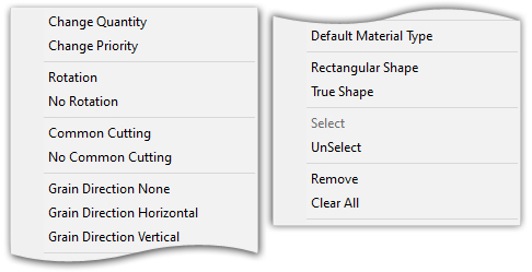
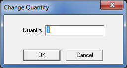
Change Quantity |
If more than one copy of a part will be used in the project, select Change Quantity from the flyout menu.
Enter the desired quantity of the part and click OK to update. Note: The program automatically decides if multiple copies of a part will be assigned to different sheets. |
Change Priority |
Change the priority of a part by entering a numeric value directly in the cell, or by selecting Change Priority from the flyout and entering the value in the dialog that appears. |
Rotation / |
By default all parts load with Yes in the Rotation column. Rotation allows the program to rotate the part as needed, while No Rotation stops it from rotating. Note: Rotation is NOT available for parts loaded from a part kit (or group). |
Common Cutting / No Common Cut.
|
By default all parts load with No in the Common Cutting column. Select Common Cutting from the flyout menu to enable Common Cutting. Note: Common Cutting is NOT available for parts loaded from a part kit (or group). |
Grain Direction |
By default all parts load with None in the Grain Direction column. Select None, Horizontal or Vertical from the flyout menu to change the grain direction. |
Default Material Type |
Select to use the default material type for the selected part. See Preferences>Default Values for choosing default settings. |
Rectangular |
If Rectangular is chosen, the program will not allow nesting inside the cutout of another part’s profile. When True Shape is selected, the program will allow such nesting. A selection made here applies to all parts in the Parts List for Nesting. |
Select / Unselect |
Click an unselected part and choose Select to hi-lite the part row. Click a selected part and choose Unselect to remove hi-lite from part row. |
Remove |
To remove a part from the list, highlight the part first and then click Remove. |
Clear All |
Clicking on Clear All will remove all parts from the parts list. Clear All will remove all parts from the list, even if they are NOT highlighted. |
Disable Preview |
In the bottom pane a thumbnail preview of the selected part is displayed. To disable the preview, check the Disable Preview checkbox. |

For information on these buttons, see Add (Load) Parts.
|
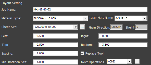
Enter values or make selections for the sheet in these fields. It's best to enter Layout Settings BEFORE parts are added to the Parts List. This will force added parts to acquire the desired config settings.
|
|
Job Name |
By default the program will enter the current
date and time that the current project was started. Keep that
as the Job Name, or assign another Job Name. |
Material Type / Laser Material Name
|
Select a Material Type to be used from the drop-down list. The Material Types available in the list also come in various thicknesses, which have been saved with each material type. Material Type choices that are available in the drop-down field come from the Material Type table, and depend upon what kind of material types have been input into the table. To review or edit material type information, hit <F6> to open the Material Type window. Click on the Edit Material button and the Edit Material dialog box opens. From the Laser Material Name pull-down, select from options available in the list. See Material Library for information
on material types, etc. |
|
|
To select a different Sheet Size click the pull-down button to open the drop-down list. Sheets in the list have already been configured in the Material Library. If two or more sheets are checked ON in the list, the Sheet Wizard will select the best sheet for the nesting job from those sheets. Before nesting be sure to verify ALL material parameters! The Material Library is the primary source for all materials used in the Sheet Wizard. If a parameter that is set in the Material Library is not set in the Parts List for Nesting, the nesting job will fail. Set parameters for parts listed in the Parts List according to the configuration in the Material Library. If a change must be made to a material, it's best to update it first in the Material Library and then update the parts accordingly.
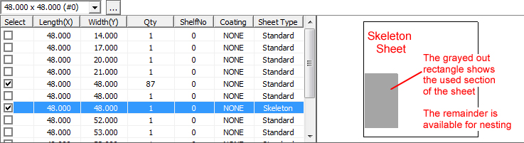
If a sheet with a skeleton is selected, the flyout on the right will show the skeleton sheet Click the button to open the Material Library. Grain Direction and Shelf # are given in two read-only fields. Note: If the Material Library button and
Grain Direction and Shelf # fields are hidden, check in the C:\AP100US\Parm
folder and open the NestWizard.ini file. The SheetWizShowMatProperty=1
line item should be set to "1" to show these items. |
Left Right Top Bottom |
Specify values in these fields to create a border around the perimeter of the sheet. The program cannot nest parts in this zone. This feature can be useful for avoiding clamps. |
Enter a value for spacing between parts on the sheet. This spacing is between the geometry of the parts, as Sheet Wizard doesn’t take into consideration tool width unless enabled in the Include Tools/Beam checkbox. |
|
Replace Tool |
When this box is checked the system will
automatically find a suitable tool if there is a problem (such
as incorrect size) with the user-assigned tool. See
Preferences>Tool Assignment>Replace Tool for full info. |
Min. Rotation Size |
To control part rotation, the user may enter a minimum rotation size. If the minimum rectangle size of the part is larger than the minimum rotation size, the part will rotate freely. If the minimum rectangle size of the part is smaller or equal to the minimum rotation size, then the part may be treated as a non-rotating part by Sheet Wizard, or may rotate only to 90 degrees. This depends on the size ratio of X to Y of the part. |
Next Operations |
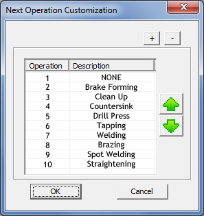
After a sheet has been completely cut or punched, the user may choose which procedure will follow. From the pull-down menu the user may select from choices such as Brake Forming, Countersink, Welding and so on. To change the order of the operations or add/delete options, click the button to display the Next Operation Customization dialog shown here -
Highlight a line item and click the green up/down arrows to change the order. Click the + button to add a new operation by entering text in the new field created at the bottom of the list. Click the - button to delete an already selected line item. |
|
Nesting parameters can be set here. |
|
|
|
Option |
Description |
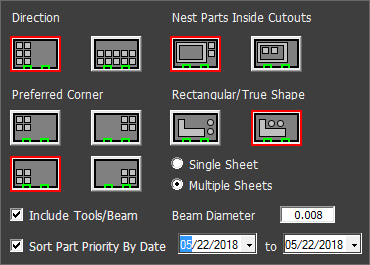
Direction |
Click on a Direction in the “x” or “y” axis. |
Preferred Corner |
Click on a Preferred Corner to select the corner to begin nesting. |
Nest Parts Inside Cutouts
|
Click on the option on the left to NOT nest smaller parts inside larger part cutouts. Click on the option on the right to permit nesting smaller parts inside larger part cutouts. |
Rectangular / True Shape
|
If Rectangular is chosen, the program will not allow nesting inside the cutout of another part’s profile. When True Shape is selected, the program will allow such nesting. A selection made here becomes the global setting applies to all parts in the Parts List for Nesting. The same setting found in the Machine>Sheet Layout Info panel is synchronized with this setting. |
|
Multiple Sheets
|
Select an option to enable the program to complete the project in one or multiple sheets as needed. If Multiple Sheets is chosen, the program will add a -1, -2 and so on to the name of each sequential sheet. In addition, the NC code for each sheet will match based on the job name. |
Check ON the box and the program will add Tool Width to Spacing (See Layout Setting>Spacing) when punching. In laser cutting it will include Beam Diameter and Lead-in/out length. Beam Diameter The Beam Diameter shown here comes from the material beam offset. Update the Beam Diameter here if needed by entering a new value. |
|
Sort Part Priority By Date |
To give nesting priority to parts within a certain date range, check ON the checkbox and then select the necessary "from" and "to" dates. Parts within the date range will be nested before parts that have been assigned an earlier due date in the Parts List for Nesting>Due Date column. If this option is checked OFF parts will still be nested according to the Due Date set above (an earlier due date first has a higher priority). Note: For this option to function parts must have been assigned a due date. |