The options in the Default Values panel allow you to specify the default operating conditions for the AP100US System. You can set the measurement units, import parameters, sheet size and thickness, numerical formatting, cursor and grid properties, and the tooling and cutting files.
You can access the options in each panel by clicking the corresponding icon in the navigation bar along the left side of the window. (Note: The panels that display on the menu bar at the left vary depending upon the machine that you have running.)
Save |
Make sure to click the Save button if you modify any of the options in the Preferences window. |
OK |
Click OK to close the window after you save your preferences. |
Cancel |
Click Cancel to close the window without saving any changes. |
Option |
Description |
Setup Directory |
The software configures this option during installation. If you alter the name, drive or path, you must configure a setup directory by clicking the navigation button to the right of the field to locate the new system and \Parm (Parameter) directories. |
These options in this section allow you to specify either inch or metric values throughout the programming process and NC code generation. |
|
Current Units |
Select Inch from the Current Units drop-down menu to view all measurement units in inches. Select Millimeter from the Current Units drop-down menu to view all measurement units in metric. |
Grid Spacing |
Type a value to set the default grid spacing for the cursor. |
Cursor Step |
Type a value to set the default cursor step. |
|
Note: If you type 0.010 in the Grid Spacing and Cursor Step text boxes, the cursor will move at an incremental stop value of 0.010. If you specify a value of zero, the cursor will not jump. |
Digits Number of Values |
Type a value for the leading and trailing digits for linear dimensions. |
Digits Number of Angles |
Type a value for the leading and trailing digits for the angular dimensions. |
Dimensioning Font |
The Dimensioning Font option allows you to select a typeface for the dimensioning features. Clicking the navigation button to the right of the font name will open a standard Font dialog box. You can then select the font you want to use when you dimension your parts and sheets. |
Scribe/Etch Font |
Using complicated True Type fonts can add a lot of extra geometry, etching time and code. With Use Simple Text checked ON (the default), the program will automatically choose a Simplex font when scribing and etching. |
Import Parameters |
The options in the Import Parameters section allow you to specify the conversion parameters for those CAD files you import into the software. |
Units of File |
Select Millimeter from the Units of File drop-down list to preserve the metric values. Select Inch to preserve the inch values or to convert metric values to inch values. |
The Check Layers option allows the software to detect layer names in DXF, DWG, IGS and CDL files. You can then discard unwanted layers or convert layers to solid or construction lines. (See Importing Layers.) |
|
Check here to enable an OLE preview. Note: Working together with programs such as SolidWorks, SolidEdge and Pro/E, OLE automatically calls the unfolding module, flattens the 3D model and then passes the flattened part with certain bend information to the AP100US program. For more background on OLE, please see Modules, SolidEdge®, SolidWorks® Integration, Pro/Engineer® Integration and Autodesk Inventor Integration. |
|
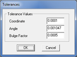
Tolerances… |
Allows you to modify the variables used for geometry cleanup when importing CAD files created in other applications. Click the Tolerances button to adjust the Coordinate, Angle and Bulge Factor values. The ANGLETOLERANCE=, COORDTOLERANCE= and IMPBULGEFACTOR= values in the WIN.INI are updated to reflect the changes after you click OK.
|
|
Coordinate - This option allows you to specify a value for the maximum tolerance for coordinates and distances for the imported CAD drawing. The default value is 0.0001. Angle - This option allows you to specify a value for the maximum tolerance, in degrees, for the angles in the imported CAD drawing. The default is 0.001047. Bulge Factor - Certain entities, such as splines, conic arcs, ellipses, parabolas, etc., are not true arcs and are often imported as lines. You may want to check this setting if you are importing a part that contains spline entities. The default value is 0.0005. AP100US imports and divides splines as a series of arc and line patterns. The smaller the value, the greater the accuracy and the software will divide the spline into a greater number of arcs or line segments. The higher the value, the lower the accuracy and the software will divide the spline into a smaller number of arc or line segments. |
Allows you to configure AP100US to recognize the various line types used by other CAD systems. This allows you to reduce the amount of time necessary to delete lines or to convert line patterns to construction lines, thereby preventing the software from assigning tools to bend or reference lines. (See Importing Linetypes.) Note: When any other type than “Continuous” or “Solid Line” is detected in a DWG, DXF, IGS or IGA file, AP100US converts those lines into the “Construction” line type. Otherwise, you can control which line types you prefer to save with the preferences. |
|
This option allows you to configure the import parameters for the Pro/Engineer environment. (See Pro/E Import Configuration.) |
|
This option is used to set the default format for exporting an XLS file when generating a nested sheet, or Export Sheet Data To XLS. Available
formats are displayed in the drop down list. The Output Format
window displays when you click the browse button Please refer to Using the XLS Option on how to make and modify the format to output. |
|
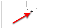
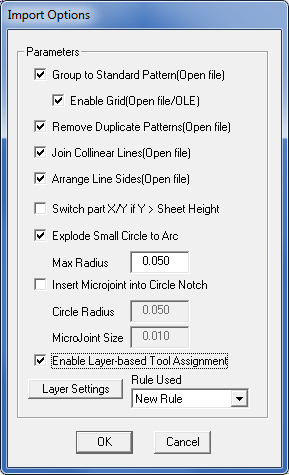
The options in the Import Options dialog allow you to specify the conversion parameters for those files (such as .dxf or .dwg) you import into the software. Check ON to enable a grid for Open File / OLE. The Group to Standard Pattern and Enable Grids options determine whether the system attempts to convert standard pattern or pattern grids when you import DXF file. The Remove Duplicate Patterns option removes any pattern that is completely covered by another pattern when you load DXF file. When you enable the Join Collinear Lines option, the system will locates overlapping lines or end-to-end lines and converts them into a single line. The option deletes the first line and adjusts the second line to occupy the entire space. The Arrange Lines Sides option allows you shift the line sides on groups of patterns identified as loops so that all the sides match. Click OK to apply the above settings when you load DXF files. When Switch part X/Y if Y > Sheet Height is checked ON, if the loaded part in Y is greater than the sheet height, then the part being imported will rotate automatically to fit the current sheet. Check On the Explode Small Circle to Arc checkbox so the user can set a max radius value for the circle. If the radius is smaller than this value, the circle will be exploded into an arc when loading dxf/dwg files. Insert Microjoint into Circle Notch allows the user to insert a microjoint into a circle notch cut out of the part perimeter. Check the box to enable and enter values as needed.
Enable Layer-based Tool Assignment gives the user the ability to have certain software behaviors (such as Etching) occur to CAD elements that exist on a certain Layer within the loaded DXF/DWG file. The Rule Used drop-down allows the user to select from previously configured rules that may be applied to a file. For more info see Enable Layer-based Tool Assignment below.
|
|
|
|
Check ON the Sheet/Part Association option and when a sheet is opened in the AP100US work area, the system will check if any parts on the sheet were modified after the sheet was created. If any changes have occurred, the Modified Part List will display, allowing the user to select which version to load onto the sheet. |
|
Sheet Size Defaults |
The options in this section allow you to specify the default sheet size and thickness. |
Width |
Enter a value for the default width of the sheet. |
Height |
Enter a value for the default height of the sheet. |
Thickness |
Enter a value for the default sheet thickness. |
Punching and |
The options in this section allow you to specify the default files the software is to load during startup. |
Cutting Default Files |
|
Machine
File, |
The Machine File, Tool Inventory, Material File, Material Group, and Material Type options allow you to define the default machine setup, tool inventory, material file, material group, and material type to load when the system opens, or when you create a new sheet. You can locate the desired files using the navigation buttons found to the right of each field. If you have not yet created or installed these files, you can select them later. |
NC Path |
This field displays the current file path where the system stores the NC program files. Click the navigation button to open the Browse for Folder dialog and select an alternate location if needed. Select the directory name and then click OK in the dialog. This field also appears in the Machine Settings>Description panel. If the NC Path field here in Preferences>Default is checked ON, then the program will use this NC Path as the default path, overriding the NC Path in Machine Settings>Description. If the field is NOT checked on the system will use the path that is set in the Machine Settings panel. Ext
|
Machine Setup |
This field displays the current file path where the system stores the machine setup info (sheet size, part information, date and time the program was created, NC file name and sheet file name). Click the navigation button to open the Browse for Folder dialog and select an alternate location if needed. Select the directory name and then click OK in the dialog. This field also appears in the Machine Settings>Description panel. If the Machine Setup field here in Preferences>Default is checked ON, then the program will use this Machine Setup as the default, overriding the Machine Setup in Machine Settings>Description. If the field is NOT checked on the system will use the path that is set in the Machine Settings panel. Ext |
|
|
Print Settings
|
Displays the Print Settings dialog box. (See Print Settings.) |
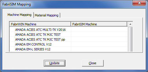
FabriSIM Mapping |
To create or modify the mapping between AP100US and FabriSIM click the FabriSIM Mapping button to open the FabriSIM Mapping dialog shown here -
Use either the Machine ID or Driver Name to match to the FabriSIM Machine. If Machine ID is selected, the Combo Box for AP100US Machine will list all mapped machine ids (the default should be the current machine). After one machine id is selected, the FabriSIM Machine field will display the matched machine name. The user also can input a new machine id, and select a FabriSIM machine to map with it. If the user selects the Driver Name, the Combo Box for the AP100US Machine will list all mapped driver names for the user to modify (the behavior is the same as Machine ID). After the user clicks the “Update” button, the modified/created mapping will be saved. Note: FabriSIM only supports Amada machines. Mapping to non-Amada machines may not function. Note: The user must have a valid FabriSIM Gcode Simulator/Editor license for this function to work properly. |
Auto Save |
This option allows the user to set the interval by which the current project in the AP100US Work Area will be auto-saved. The zip file is saved to the AutoSaveFiles folder in the AP100US installed folder, is updated as work progresses and is deleted when a work session is terminated normally. These files can be accessed as needed for recovery after a program failure, or to be shared with other programmers. |
The following entries describe certain options outlined above in greater detail.
Enable Layer-based Tool Assignment
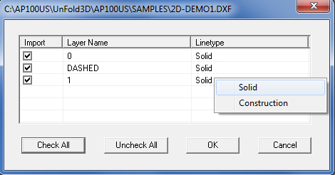
If you enabled the Check Layers option in the Default Values panel of the Preferences window, when a DWG, DXF, IGS, or CDL file is opened in the AP100US work area, the software will automatically examine the files for multiple layers. If the system detects multiple layers within the file, the Import Layers Control window will appear. The Import Layers Control window will list those linetypes found in the file. The window consists of Import, Layer Name, and linetype controls.
|
|
Option |
Description |
Import |
The check boxes in the Import column allow you to select which layers to import. If you place a check mark in the check box for a particular Layer Name, the system will import the layer. If you remove the check mark, the software will not import the layer. |
Layer Name |
The actual layer names appear in this column. |
Linetype |
The actual line types, Solid or Construction, appear in this column. |
Check All |
Click Check All to choose all the layers for conversion. Check marks appear in all the Import check boxes next to the layer names. |
Uncheck All |
Click Uncheck All to remove all the check marks from the Import check boxes. |
Solid / Construction |
You can select a line type name in the linetype list and then click the right mouse button to open a shortcut menu. There are two options: Solid and Construction. You can then convert the currently selected layer in the window by selecting Solid or Construction. |
Linetypes |
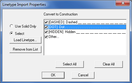
If you want to configure AP100US to recognize and automatically convert the linetypes in DWG, DXF, IGS, or CDL files, click the Linetypes button in the Import Parameters section of the Preferences window. The Linetype Import Properties dialog box allows you to define those linetypes you want the software to convert to construction lines.
|
|
|
||
Option |
Description |
|
Convert to Construction |
This window lists the selected linetypes that will be converted to construction lines when the software imports the file. |
|
Use Solid Only |
This option converts all the linetypes that the system imports into solid lines. |
|
Select |
Select this option to choose specific linetype files for the conversion process. |
|
Load Linetype… |
Click this button to open the Load Linetype dialog box. (See Loading Linetype Files.) |
|
Remove from List |
Select a linetype in the Convert to Construction list, and then click the Remove From List button to remove the linetype. |
|
Select All |
Click Select All to choose all the linetypes in the Convert to Construction list for the conversion process. |
|
Clear All |
Click Clear All to remove all the check marks from all the linetypes in the Convert to Construction list. |
|
|
|
|
Load Linetype |
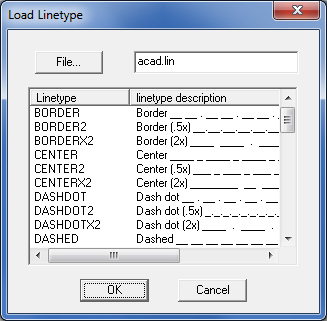
To load specific linetypes for conversion, click the Load Linetype button in the Linetype Import Properties dialog box. The Load Linetype dialog box allows you to select specific linetypes contained in a user-defined ASCII text file or an AutoCAD *.lin file. |
|
Click the File button. The Open dialog box appears. Navigate to the desired folder, select the linetype file, and click Open. The linetypes contained in the file are listed in the dialog box. You can use the Control + click or Shift + click technique to select the linetypes. When you are finished selecting linetypes, click OK in the Load Linetype dialog box. The selected linetypes appear in the Linetype Import Properties dialog box. |
|
|
Pro/E Config |
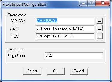
To view or modify the Pro/Engineer environment settings, click the Pro/E Config button in the Import Parameters panel of the Preferences dialog box. The Pro/E Import Configuration window appears. The window is divided into Environment and Parameters sections. The Environment section allows you to specify the path for AP100US, the Java Runtime Environment and the Pro/Engineer application directory. You can type a default bulge factor value in the Parameters section. |
|
|
Option |
Description |
Environment |
Use the options in this section to specify the Pro/E environment settings. |
CAD/CAM |
Type the path to the CAD/CAM System directory, or click the button to the right and navigate to the directory. |
Java |
Type the path to the Java Runtime Environment directory, or click the button to the right and navigate to the directory. |
Pro/E |
Type the path to the Pro/Engineer application directory, or click the button to the right and navigate to the directory. |
Parameters |
Use the Bulge Factor text box to specify a bulge factor. |
Bulge Factor |
Type the bulge factor you want to use for importing Pro/E files in the text box. |
Detect |
Click the Detect button to automatically detect and configure the Pro/E environment settings. |
OK |
Click OK to save any changes. |
Cancel |
Click Cancel to exit without saving any changes. |
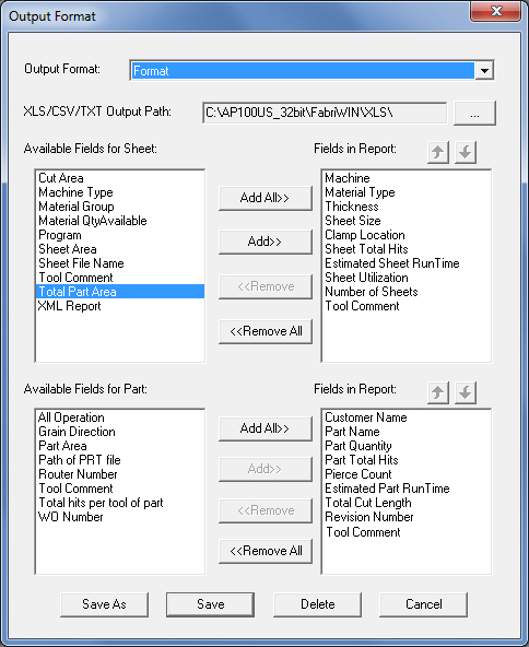
Using the XLS OptionClick the browse button beside Export XLS to open the Output Format window. The user can define and choose the format desired. Formats designed can be saved for future use, and can be modified as well.
|
|
|
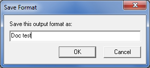
If you have not used the Output Format before and there is no format available, a certain format should be defined first. When you click the Add All or Save As buttons, a message window prompts you to name an Output Format.
|
|
Once the format is named and saved, select the fields of Sheets and Parts that are to be included in the format, and Save them. For the Available Fields of the Sheet or Parts, you can click the Add>> button to add the fields one by one, or you can click the Add All>> button to add all the fields at one time. |
|
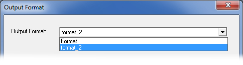
The
Fields In Report can be reordered by clicking the up and down
arrow buttons You can modify and save the current format with a different name. all available formats will be displayed by selecting the pull-down arrow in the Output Format field.. |
|
|
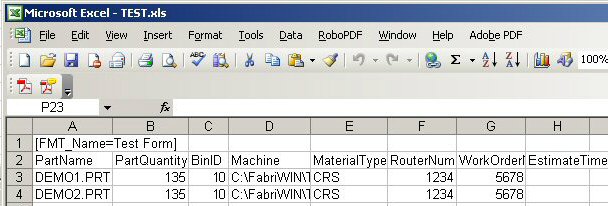
The XLS file that will output after will resemble this table: |
|
This XLS file can be viewed after a nested sheet is generated. |
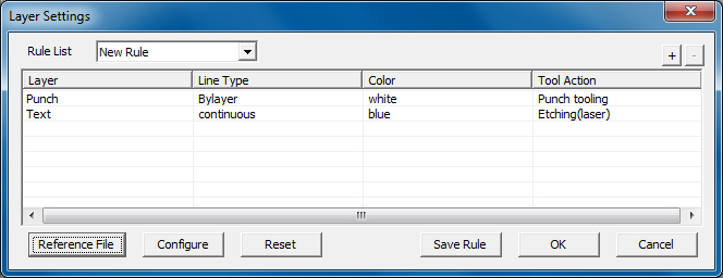
When the Enable Layer-based Tool Assignment box is checked ON, and the Layer Settings button is clicked the Layer Settings window appears -
|
|
|
|
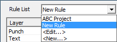
| Rule List | This drop-down contains a list of existing rules. The user may click <Edit> to remove or Rename an existing rule, or <New> to create a new rule.
|
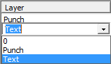
| Layer | Double-click
a row in the Layer column to show the drop-down. Select a different
name from the list, edit an existing name or type in a new one
(by selecting an existing name and typing over it).
|
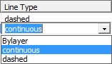
| Line Type | Double-click
a row in the Line Type column to show the drop-down. Select a
different name from the list, edit an existing name or type in
a new one.
|
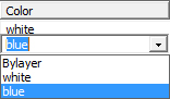
| Color | Double-click
a row in the Color column to show the drop-down. Select a different
name from the list, edit an existing name or type in a new one.
|
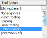
| Tool Action | Double-click
a row in the Tool Action column to show the drop-down. Select
a different name from the list, edit an existing name or type
in a new one. This is the only column that contains fixed default
data, which cannot be altered.
The
Direct Reference action forces a part to rotate to match the grain
direction of a sheet. |
Reference File |
Click
the Reference File button
to open the window to select the dxf or dwg file being referenced.
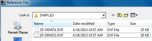
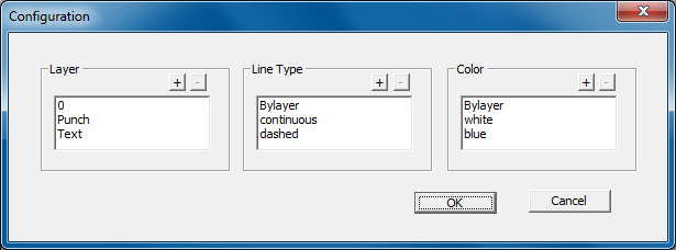
When a dxf or dwg file is selected, the data from that file will populate the Layer and Line Type sections of the Configuration dialog (as shown below). |
Configure |
Click
Configuration to Create (click the +
sign)
and / or Delete (click the -
sign)
Layers, Line Types and Colors.
|
Reset |
Clicking
Reset will
permanently delete settings in all columns for a selected rule.
Be Careful - this cannot be reversed!
|
Save Rule |
Click
to save changes to any rule, or a newly created rule.
The system will display a warning window if the user attempts to save before all columns are completed. |
OK / Cancel |
Click
OK to
save or Cancel to close
the window without saving any changes.
The system will display a warning window if the user attempts to save before all columns are completed. |
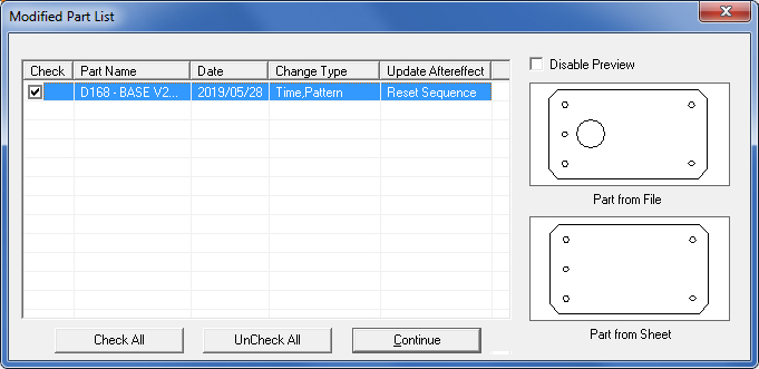
If there are no changes, the sheet will load as before. If one or more parts have been changed on the sheet to be loaded, the Modified Part List dialog box will appear, prompting the user to choose which modified part(s) to load. Leave the part checked ON (the default) to place the version of the part with the most recent change on the sheet. To have the older part version remain on the sheet, uncheck the part. Click Continue to execute. |
|
|
|
Check |
This column allows multiple parts to be chosen for modification. |
Part Name |
This column lists all parts which have changes made to the geometry, tools, or certain pattern conditions. |
Date |
The date that the part was changed. |
Change Type |
Displays the type of change that occurred. Pattern - Indicates a change to part geometry. Tool - Indicates a reassigned tool (no change to geometry). Attribute - Indicates a change to pattern’s condition or attribute. |
Update Aftereffect |
Displays the result whether the sequence will be kept or reset when loading the sheet file. The result will be either “keep sequence” or “reset sequence.” |