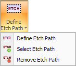
The Define Etch Path, Select Etch Path and Remove Etch Path options on the Etch submenu allow you to manually define patterns you want to etch. The Etch Text option allows you to assign cutting conditions to the etching paths. Patterns that have been selected for etching, will remain as etching paths even after the sheet or part has been processed.
To convert a cutting path or paths to an etching pattern or patterns, select Define Etch Path from the Etch submenu. Move into the work area. The prompt in the message window instructs you to select the path or paths you want to convert.
Move the crosshair near the pattern or group of patterns. Click the left mouse button to start the marquee. Drag the marquee around the pattern or patterns. When the marquee encloses the pattern or patterns, click the left mouse button again. The path changes to the etching color you selected in the Etching section of the Material File window.
Notes:
1. You must select the entire path. If you fail to include the entire path, it will not be defined as an etch pattern.
2. Only the Etching conditions, Start Cut Attribute, End Cut Attribute and Pierce Location you specified in the material file are retained after you define the etching path. The system ignores any lead-ins, lead-outs, or other cutting conditions.
3. The system etches directly on the pattern line or shape.
The Select Etch Path option on the Etch submenu allows you to manually select any path you want to convert into an etch pattern. After selecting the option, move the pointer onto the path and click the left mouse button. The path changes to the etching color you selected in the Etching section of the Material File window.
Note: You can also edit a Start Cut Attribute to select a path for etching. You can select the attribute and substitute the Etching range for the cutting range. The path will change to the etching color and is setup to etch.
The Remove Etch Path option on the Etch submenu allows you to convert etch patterns into cutting patterns. After selecting the option, move the pointer onto the etching path and click the left mouse button. The path changes to the pattern color.
Note: You must add a Start Cut Attribute to the path after converting the etch pattern to a cutting path.
![]() The Etch Text option on the Etch submenu
allows you to create and generate an etch path and assign a cutting condition
to the text. The Scribe/Etch Text window allows you to define the parameters
for the text and place the text in the work area. See
Scribe/Etch Text Window.
The Etch Text option on the Etch submenu
allows you to create and generate an etch path and assign a cutting condition
to the text. The Scribe/Etch Text window allows you to define the parameters
for the text and place the text in the work area. See
Scribe/Etch Text Window.
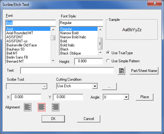
The Scribe/Etch Text window allows you to specify the properties for the text that you want to etch, assign cutting conditions to the patterns, and place the text in the work area. In this window enter and configure the text as desired and select a scribe tool. The user may also click Part/Sheet Name to insert the name of the current part or sheet into the Text: field. For more info see Scribing Tool Info. |
||
|
||
Option |
Description |
|
Font List |
The Font List displays all the fonts that are currently installed on your computer system. You can scroll through the list and select the desired font for the etch text. |
|
Font Style List |
The Font Style list allows you to apply a style, i.e., Regular, Italic, Bold or Bold Italic to the etch text. |
|
Sample |
The Sample area displays a thumbnail image of the selected font and font style. |
|
Height |
Type a value for the text height in this field. |
|
|
Note: Due to the many different styles of fonts, the actual vector reproduction may vary from the actual value you specify in the Height: text box. |
|
Use TrueType |
If you select Use TrueType, the system will assign the etch or scribe tool directly on the patterns consisting of TrueType fonts without any left or right line compensation. |
|
|
|
|
Use Simple Pattern |
If you select Use Simple Pattern, the system will use line compensation to generate contiguous line and arc patterns that are a simplified form of the TrueType font being used. |
|
|
|
|
Text Field |
Type the desired scribe or etch text in this field. |
|
Recall Button |
|
Click the Recall button or press <F3> to restore the any text that you previously typed in the Text: field. |
Scribe Tool |
Click the Scribe Tool arrow button and select a scribe or etch tool from the drop-down list. This list will only display those tools that you have designated as scribing tools. You must enable the Use For Scribing option in the Station Tool Information window to designate a tool as a scribing tool. See Machine Files, Station Tool Information Window. |
|
Cutting Condition |
This option is available if you have a cutting or combination machine that supports cutting conditions for etching. The Cutting Condition list allows you to access the default, etching and range checking values that you defined in the material file. See Chapter 13: Material Files, Condition Tables Panel and Chapter 14: Tool Assignment, Scribe Text Tool. |
|
|
|
|
X |
The X coordinate of the etch text. |
|
Y |
The Y coordinate of the etch text. |
|
Angle |
You may select one of four angles from the Angle: drop-down list: 0, 90, 180 or 270. |
|
Place |
Click the Place button if you want to manually position the text in the work area. A text box outline will follow the mouse pointer after you select Place. Move the text box to the desired position and click the left mouse button to place the text. |
|
|
|
|
Alignment |
The Left, Center and Right alignment buttons allow you to specify the origin output of the text. |
|
|
The text will be placed with the origin output to the left |
|
|
The text will be placed with the origin output to the center. |
|
|
The text will be placed with the origin output to the right. |
|
OK |
Click OK to place the etch text and to close the window. |
|
Cancel |
Click Cancel to exit without placing the etch text. |
|
|
|
|