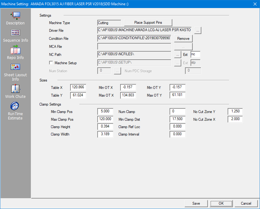
The Description panel allows you to view the table size, the total number of stations, the clamp settings, support pin placement settings, the machine driver and the default path and file name extension for the NC files.
Option |
Description |
||
Settings |
Use the options in this section to specify the general machine information. |
||
Machine Type |
This option displays the currently loaded machine type: Punching, Cutting or Combination. |
||
| Click the Place Support Pins button to open the Support Pin Placement window. (See Place Support Pins.) | |||
Driver File |
|
This field displays the current machine driver. You can click the navigation button to select an alternate driver. A standard Open window will appear and list the driver files in the default directory. If necessary, select the driver file for your machine and click the Open button. |
|
|
AP100US allows cutting conditions files (JKA, JKAX and JKF) that are taken from the control on the laser to be loaded. To select a condition file, click the After a file is loaded the Load button changes
to Clicking Remove will remove the link between this machine file and the condition file. Note: The information in the JKA, JKF, JKAX, JKM, JKMX and JKAM files is used for runtime calculations ONLY! For more info on JKA, JKF, JKAX, JKM, JKMX and JKAM files, click here.
|
||
MCA File |
|
Used with punch and combo machines, an MCA file contains conditions and Special Tool info such as tool position and speed. Click the button to load an .mca file, which, by default, is stored in the C:\AP100US\ConditionFile folder. See Turret Window - M-Code View for more info. |
|
NC Path |
|
This field displays the current file path where the system stores the NC program files. Click the navigation button to open the Browse for Folder dialog and select an alternate location if needed. Select the directory name and then click OK in the dialog. Note: This field also appears in Preferences>Default. If the NC Path field in Preferences is checked ON, then the program will use that NC Path as the default path. If the field is NOT checked on the system with use the path set in Machine Settings. Ext
|
|
Machine Setup |
|
This field displays the current file path where the system stores the machine setup info (sheet size, part information, date and time the program was created, NC file name and sheet file name). Click the navigation button to open the Browse for Folder dialog and select an alternate location if needed. Select the directory name and then click OK in the dialog. Note: This field also appears in Preferences>Default. If the Machine Setup field in Preferences is checked ON, then the program will use that Machine Setup path as the default path. If the field is NOT checked on the system with use the path set in Machine Settings. Ext
|
|
Num Station |
|
This value represents the number of tool stations or available tool slots. You can click the navigation button to open the Turret window. |
|
Num PDC Storage
|
This value represents the number of tool stations in a PDC Storage System. (See Punch Die Changer and PDC Machine Setup.) Reverse Driver File |
||
Sizes |
Use the options in this section to specify the general table information. |
||
Table X |
This value reflects what the machine manufacturer refers to as the Table Size in the X-Axis. It is also known as the maximum possible sheet size that the machine is capable of punching or cutting in the X-axis without repositioning. |
||
Table Y |
This value is the table size of the machine in the Y-axis. |
||
Min OT X |
Min OT X and Min OT Y allow you to specify a distance the table, cutting or punching head is able to travel in the negative X and negative Y direction away from the starting point. Machines that are capable of moving in the –X and –Y display the settings as negative numbers. Machines incapable of this feature display only zero settings. Note: This value is limited by the travel range of the machine in use. |
||
Max OT X |
|||
Min OT Y |
Max OT X and Max OT Y overtravels specify the furthest distance the table, cutting or punching head can move from the starting point. Type the maximum X (horizontal) overtravel in the Max OT X text box and the maximum Y (vertical) overtravel in the Max OT Y text box. Note: This value is limited by the travel range of the machine in use. |
||
Max OT Y |
|||
Clamp Settings |
Use the options in this section to specify the clamp settings. |
||
Min Clamp Pos |
This is the minimum position along the X-axis that you can place a clamp. |
||
Max Clamp Pos |
This is the maximum position along the X-axis that you can place a clamp. |
||
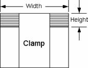
Clamp Height |
This value represents the distance from the sheet stop on your work holder to the end of the clamp (Y-axis). |
|
|
Clamp Width |
The actual width of the clamp (X-axis). |
||
|
Notes: |
||
|
For a punching system, the No-Punch Zones are added to the values. Make sure to specify accurate values. (See Turret Setup.) |
||
|
For a cutting or combination system, the No Cut Zone values are added to the Clamp Height and Clamp Width. Make sure to specify accurate values. |
||
Num Clamp |
The number of work holders or clamps. |
||
Min Clamp Dist. |
This is the minimum distance allowed between the work clamps or holders. |
||
Clamp Ref Loc |
For machines that have clamps and tools in slots in a tool rack on the carriage, this option allows you to define the first clamp to a certain position that coincides with the dimension of a tool slot. Each time you select a new sheet, the first clamp automatically moves to this position rather than centering itself on the sheet in relation to the sheet size versus the space between the clamps. |
||
|
For machines with clamp positions that proceed at defined intervals, type the starting coordinate in this text box so the system can begin measuring the interval. For example, if the clamps are 4.00 inches apart and start at 1.00 inch from the lower left corner of the sheet, you would type 1 as the Clamp Ref and 4 as the Clamp Interval. When you move the clamp, you could stop it at 1, 5, 9, 13, etc. If the Clamp Ref is 2 and the Clamp Interval is 4, you could stop the clamp at 2, 6, 10, 14, etc. Specify 0 (zero) if your machine does not use this feature. |
||
Clamp Interval |
You will want to specify a value for this option for a machine that has clamps and tools installed in slots in a tool rack on the carriage. This option defines the distance between tool slot positions on the tool rack. |
||
|
If you typed a value in the Clamp Ref text box, you would enter a value in the Clamp Interval text box to specify the interval between the clamps. The clamp jumps by this interval as you slide it to the left or right. If your machine does not use this feature, type 0 in the text box. |
||
No Cut Zone X |
For a cutting or combination system, you can define X and Y coordinates for a No Cut Zone so the cutting head will avoid the clamps. Type the horizontal or X dimension in the No Cut Zone X text box, which is the measurement from the center of the clamp to the edge of the horizontal zone that should not be cut. |
||
No Cut Zone Y |
|||
SDD Machine Mapping |
Clicking this button links the current machine in AP100US to a Machine registered in SDDJ. Data from the programs that have been stored into SDDJ can be linked to other products that link to SDDJ (such as AP100G CAM or Dr.ABE_Blank). Contact Sales Support to learn how to activate the SDDJ Server. Click for complete SDD information.
|
||
Save / OK / Cancel |
Clicking Save after making changes will save those changes as the default. Click OK to save changes only for this session (system reverts to default settings when program is closed). Click Cancel to cancel any changes and close the window. Note: When editing part conveyor size in the TK/PSR Settings window, the user should save the current machine in the Machine Settings>Description panel to save these new values as the default. |
||