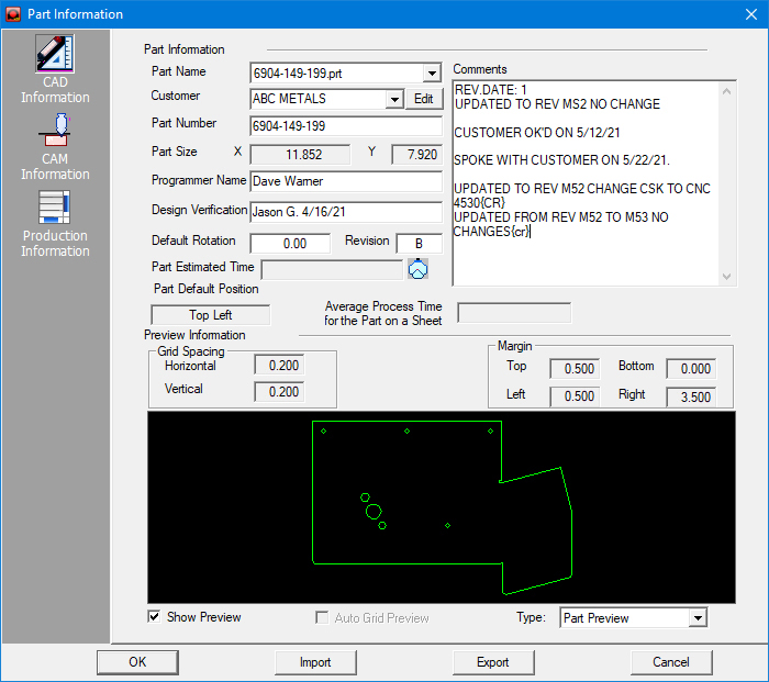
The options in the CAD
Information panel allow you to specify a part number, programmer
name, the default rotation and revision, and Part Default Position.
You can also add comments for the part. |
|
Notes: |
1. Margin,
Grid Spacing and Default Position values are transferred from
the Auto Grid Information section (Machine\Machine Info\Description)
setting |
2. The
system will select the corresponding margin value according to
the part Default Position. For example, if you choose Bottom Left
as the default part position, the system will apply the Left and
Bottom margin values for the part. |
3. The
Default Rotation angle range is from -180o to 180o.
If you type a position value, the part will rotate clockwise.
If the value is negative, the part will rotate counter-clockwise. |
4. The
part rotation will only appear if Sheet Preview (Type)
mode is active. The Default Rotation value can be saved after
you modify it. |
5. The
system will output the Part Number, Programmer Name and Comments
in the NC code file. |
|
Part
Name |
Optional. Type the part name
in the text box, or click the arrow and select a part name from
the drop-down list. When adding a new part name, the system automatically
stores it in the nesting database for future reference.
Also, the
Part Name pull-down list allows the user to switch between parts
on the sheet
that are in the pull-down list. |
|
Customer |
Entering
a name directly in this field and clicking OK in the Part Info
panel will create a new database record for a new customer.
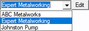
To
modify the name of an existing customer (database record) click
the Edit button to open the dialog. Select the Customer's name
from the pull-down and edit the name in the field.
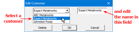
To delete a selected customer
click Delete
|
|
Part
Number |
Required field. Type the
part number in the text box. |
|
Part
Size |
Default field. The overall
dimensions for the part appear in the X and Y text
boxes. |
|
Programmer
Name |
Optional. Type the name of
the person responsible for programming the part. |
|
Design
Verification |
Here the user may enter the
name and/or number of the person who has verified the design of
this part. |
|
Default
Rotation |
The default angle of the
part when it is loaded into the system. You can type a new angle
value in the text box. |
|
Revision |
Optional field. If a part
has been revised (edited) type the revision number or letter in
this text box. A value entered here will be available in the Sheet Wizard>Parts List for Nesting,
Revision column and in the Open
File window. |
|
Part Estimated
Time |
Once
the run time for a part is calculated, the time will display in
the Part Estimated Time text-box. To update the estimate, click
the Run Time button  . .
Note: The Run Time button
is enabled only when a Driver, Tool Inventory, Machine and Part
with assigned tools or cutting path exist.
See View Run Time
for more information. Note:
The NC code must be re-generated when any changes have been made
to the part/sheet. |
|
Part
Default Position |
The default position is the
bottom left of the sheet. You can open the drop-down list and
select an alternate position: Top Left, Bottom Left, Top Right
or Bottom Right. |
|
Average
Process Time
for the Part on a Sheet |
This read-only text box displays
the Average Process Time for the Part when it is being cut/punched
on a Sheet along with other parts. The system will average out
the Part time based on various factors, such as the number of
tool hits, tool change time and repositioning. |
|
Comments |
Enter any relevant notes
that should be saved with the part in this box. |
|
Grid Spacing |
The Horizontal and Vertical
spacing for the parts in the grid.
Specify the Horizontal
and Vertical spacing for the parts in the grid. |
|
Margin |
The intervals between the
part and sheet sides. Specify the parameters for the Left,
Right, Top and Down edges for the auto grid. |
|
Show Preview |
This option is a toggle.
If you place a check mark in the check box, the Preview area will
display the part or the part in relation to the sheet. |
|
Auto Grid Preview |
This option is a toggle.
If you place a check mark in the check box, the auto grid result
will appear on the sheet. |
|
|
|
|
Type |
Select the desired Preview
type from the drop-down list: Part Preview or Sheet Preview. |
|
OK /
Cancel |
Click OK to apply the settings
to the current part and to exit the Part Information window.
Click Cancel to exit without saving any changes. |
|
Import |
Clicking the Import button
displays the Open>Parts dialog box.
In addition to standard inv
files, the user may choose to load from Tool Inventory files in
.XLS or .CSV formats. From here it is also possible to create
and edit .xls and .csv files. See Export
below for more info on this. |
|
Export |
To export Tool files in .XLS
or .CSV formats, click Export.
The Save As dialog will open allowing the user to save directly
to the TOOLINV folder in the AP100US installed folder in either
.xls or .csv format.
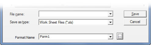
The Save As folder contains
a Format Name and button. The user may select from existing formats,
or click the button to open the Format Options window to create
or edit formats.
See Exporting Files
in XLS or CSV formats in the Material Files folder for more
info on creating and editing .xls and .csv files. |