The Color Parameters panel allows you to modify only those colors associated with AP100US System objects. The Windows® operating system controls the remaining colors for the work area, window frame and the message text and font. You can only alter these system colors by using the Display Properties option in the Control Panel. Please refer to your Microsoft Windows® documentation for changing the appearance of your desktop.
If the system displays the part borders, the parts appear in different colors, depending on which part is the selected or active part. Differentiating these colors may be a problem until you create a sheet layout. You should become familiar with the colors before you begin moving parts to layout the sheet. (See Sheet.)
Notes:
1. Exercise caution when modifying colors. For example, if the background is a dark color, the dimensions or cursor may be invisible. Use contrasting colors for your background and the objects that appear within the work area.
2. You can control whether the part borders appear by enabling Border On in the Display Options panel. (See Display Options.)
Option |
Description |
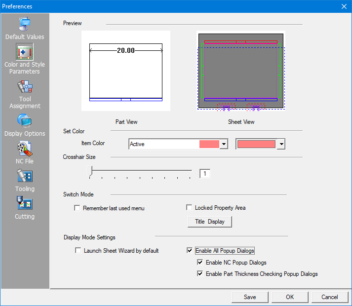
The Preview section contains two thumbnail images: PART View and SHEET View. As you select items and colors from the drop-down lists in the Set Color section, the thumbnail images update to indicate the result of the various selections in the panel. See Part View and Sheet View for more info. (See Set Color.) |
|
The options in the Set Color section allow you to define the colors for the system objects. |
|
Item List |
Select an item from the drop-down list. This list contains a set of CAD/CAM interface objects. |
|
|
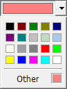
Item Color |
Select the desired color from the drop-down list. The selected color is applied to the interface object that currently displays in the Item List. |
|
|
The Crosshair Size section and slider control modifies the thickness of the crosshairs in the work area. You can click and drag the slider to adjust the crosshair thickness, or type a value in the field to the left. The value is measured in points. The range is 1 to 9 points. |
|
|
|
Switch Mode |
|
Locked |
The Locked Property Area option is a toggle. You can use this option to restore the Property Area (the blank margin along the right-hand side of the window) where the property windows used to display in previous versions of the software. If you place a check mark in the check box, and have selected the Modern Style menu type from the Menus and Toolbars drop-down list, the system restores the Property Area along the right-hand side of the application window and suppresses the fly out window.
|
Title Display |
With the Title Display button, the user can enable or disable elements such as the file name, which lists in the title bar of the open AP100US system window. The user is also able to adjust the display order in the title bar.
|
|
|
Display Mode Settings
|
Use the options in this section to enable certain display options. |
Launch Sheet Wizard by default |
Check this box to enable the Sheet Wizard nesting program to launch automatically every time the AP100US program is launched. |
Enable All
Pop |
Select this option to enable all popup dialogs. It has two sub options. Enable NC Pop-up Dialogs: Select this option to allow the NC code dialogs to pop up. Enable Part Thickness Checking Popup Dialogs: Select this option to prompt the user if the part thickness and the sheet thickness are not the same.
|