Users may customize the Ribbon Interface by changing icon style and placement.
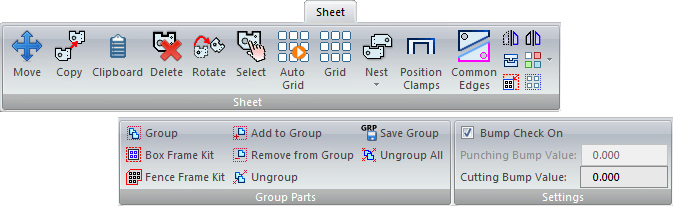
Sheet Ribbon tab
Users may customize the Ribbon Interface by changing icon style and placement.
|
|
|
|
The Move option allows you to relocate a part. To move multiple parts at one time, click this button and, while holding down the <Shift> key, drag out a box around the parts to be moved. Finally, release <Shift>, click once to show the box, relocate as needed and left-click to place.
Click for more Move Part info.
|
|
The Copy option allows you to duplicate the part to other locations on the sheet. To copy multiple parts at a time, click this button and, while holding down the <Shift> key, drag out a box around the parts to be copied. Finally, release <Shift>, click once to show the box, relocate as needed and left-click to place.
Click for more Copy Part info.
|
|
Place parts from an existing sheet into a buffer area so that they can be copied onto other sheets.
Click Clipboard to will display the Clipboard panel on the right side of the work area. To add parts to the clipboard select individual parts, or drag out a box or fence to select multiple parts.
Click for more Clipboard info.
|
|
The Delete option on the Sheet menu removes a selected part from the sheet. To delete one or more parts at a time, click this button and, while holding down the <Shift> key, drag out a box around the parts to be deleted. Finally, left-click one more time to delete.
Click for more Delete Part info.
|
|
This option rotates a part around its origin.
Click for more Rotate Part info.
|
|
Select this option to select a part.
Click for more Selecting Parts on the Sheet info. |
|
The Auto Grid option allows you to specify the parameters for creating a part grid by typing values in the Auto Grid Properties Window.
Click for more Auto Grid info.
|
|
Use the Grid option if you prefer to grid a part manually in the X and Y direction.
Click for more Grid info.
|
|
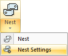
Use the Sheet nesting options to nest a single sheet directly in AP100US. Based on the Sheet Wizard nesting engine, this scaled-down option allows AP100US to make most of the nesting decisions.
Click Nest Settings to open the Machine Settings>Sheet Layout Info panel to make changes to the layout of the sheet. Click Nest to open the Nesting Part Information window to enter nest settings.
Click for more Sheet Nesting info.
|
|
The Position Clamps option allows you to move the clamps around the sheet.
Click for more Position Clamps info. |
|
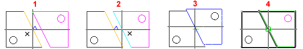
Use this option to select and join two parts for Common Cutting. 1) Click the edge of the first part to set it as the Reference edge. (A small triangle appears indicating the Reference Edge.) 2) Click the edge of the second part and it will snap (3) to the Reference edge. Adjust the location of the second part by dragging and (4) click to finalize; the two parts will be processed in the same Common Cut.
Be sure that Straight Edge Cut is ON in the Common Cutting Settings dialog. The size of the Common Cut is controlled by the Beam Diameter setting in Common Cut Settings, which is synchronized to the Pierce Location>Cutter Compensation>Beam Diameter setting. To enable Snapping click the right mouse button.
|
|
This option allows you to flip a part around a selected origin.
Click for more Flip Part info.
|
|
The Align option on the Sheet menu allows you to arrange parts next to each other at a specific distance. The system aligns one part against another.
Click for more Align info. |
|
A mirror is similar to a flip except that the original part remains and a copy appears in the quadrant of your choice.
Click for more Mirror Part info.
|
|
To modify a single instance of a part without affecting the remaining instances of the same part, use the Separate option to convert it to a stand-alone part. Parts must be ungridded and ungrouped.
Click for more Separate Parts info.
|
|
To save material on a large sheet with only a few nested parts, click the Fit Sheet to Parts icon. So doing automatically fits the sheet to the layout of the nested part(s).
See Fit Sheet to Parts for more info.
|
|
To place two or more parts into a grid on an ungridded sheet, select the Box Grid option and then drag out a box around the parts to be gridded. Note: Similar parts must be evenly spaced for this option to take affect.
See Box Grid for more info.
|
|
|
|
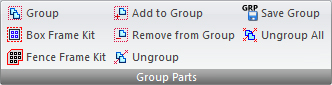
The Group Parts options allow the user to group parts that are often cut together. These groups can be saved and easily reused for recurring jobs. When cutting the sheet, the system recognizes a part group (or Box/Fence Frame Kit) as a single part, and will cut it within the normal sequence for that sheet.
See Sheet>Part Grouping for complete info.
|
|
To define a series of parts as a group, click the Group option on the Group Parts submenu. Drag out a simple rectangle to enclose the parts to be defined as a group.
Note: With the Group option when the mouse is released the rectangle will disappear; however, the parts specified are still enclosed in the group.
|
|
Select this option to create a part kit. It is ideal for small parts that may accidentally get dropped between the slats on the cutting table or are too small for automatic part removers to handle. Box Frame Kit creates an outer boundary for the part kit that will be recognized by the system and cut out along with the parts in the kit themselves.
|
|
Use this option to customize the kit boundary. Left-click to place the various points for the fence frame, right-click to join the lines and left-click again to finalize the boundaries of the fence frame kit.
|
|
At any time the user may add a part to an existing group. Click the Add to Group button, left-click anywhere in an existing group to select that group, and then left click the part to be added. The dialog will open with the "Part added to group" message - click OK to acknowledge. Parts must be added to groups one at a time.
|
|
Remove a part from an existing group by clicking the Remove from Group button. Left-click in an existing group to select that group and then left click the part to be removed. Parts must be removed from groups one at a time.
|
|
To ungroup all the parts in a group, click the Ungroup Parts button and click anywhere within the group. Respond Yes in the prompt to confirm the ungrouping. Other groups on the sheet will not be affected.
|
|
If a group will be reused at a future time, then save it to the AP100US installed folder (such as C:\AP100US\GROUP) as a .grp file. This file may be opened again and edited as often as needed. Place such files on a new empty sheet, or on a sheet with other parts.
|
|
This option ungroups all groups that have been created on the sheet. Click the button and respond Yes in the prompt to confirm the action.
|
|
|
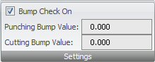
Whether one or both fields are active depends upon the machine driver that is loaded |
Place a check in the box to enable the Bump Check feature. Bump Check On allows a zone or protective border to be placed around a part.
A value entered here will update a bump zone value already entered in the Preferences > Tooling or Preferences > Cutting panel.
Click for more Bump Check On info. |
|
|