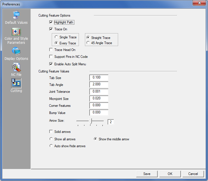
The options in the Cutting panel define the default settings for the various cutting features. You enable an option by placing a check mark in its check box. You can also type values into the text boxes to define parameters for the cutting features.
Cutting Feature Options
The options in this section allow you to specify the default behavior of the system when creating cutting or combination sequences.
Highlight Path controls whether the path or a single pattern highlights when you are using cutting or combination sequencing commands. Paths can only highlight on combination systems if you have assigned cutting tools to the patterns. To highlight the entire path, enable the Highlight Path option. If you do not want to highlight the cutting path, remove the check mark from the check box.
Trace ON allows the user to view the movement of the machine head when it is not cutting. A line drawn from one pierce location to the next pierce location indicates head travel. Enabling the option displays the trace line. When disabled, the trace line is hidden. Trace lines are not cut; they only indicate the direction the machine head is moving in.
Note: This option works with both Punching and Cutting machines.
By default Every Trace displays the trace line for every move in the sequence. If there are many patterns that cause a great deal of clutter, try selecting the Single Trace option, which will display only the trace line for the last pattern sequenced.
The user may also select between Straight Trace Line (default) and 45° Angle Trace Line, which gives a more accurate indication of the actual punch head movement.
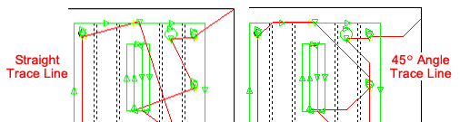
45°
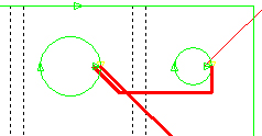
Trace line can be used to show possible collisions,
such as when the head passes near sheet clamps
A trace line may also be edited (by clicking and dragging a segment) by selecting the Sequence Features>Sequence Settings>Edit Trace Line option.
Trace Head On controls whether the sequencing path displays as a line that is slightly thicker than the trace line. This is important for machines that allow the head to “rapid-move” without lifting it. The special sequence items in the machine driver must support this option. Note: For this option to function, Cutout Avoid On must be enabled.
Support
Pins in NC Code
The
Support Pins in NC Code option controls whether a diagram of the support
pins is included in the setup sheet below the NC code in your program.
See the Place Support Pins option in Machine>Description panel for more info.
Enable Auto Split Menu
Enable this option to display the Split
Cutouts submenu on the Cut Sequence menu. This checkbox only displays
when the default Slug Destroy option has been switched OFF and the Split
Cutouts option has been switched ON. For more info see Split
Cutouts.
Tabs function like microjoints, but they can be applied only to the ends of a part perimeter or pattern cutout. This option allows the user to specify a default value for cutting tabs. A positive tab shortens the cutting path (notice the uncut section in black), while a negative tab lengthens the path. After clicking the icon, enter a value in the Tab Size panel and then click on the line that is to be shortened or lengthened. To clearly see the effect, sequence the part. For more info see Tabs and Tab Angles.
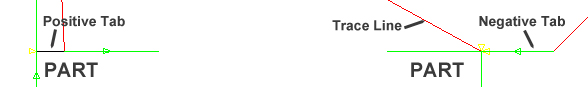
Tab sizes have been exaggerated for effect
Like regular Tabs, this option allows tabs to be placed on arcs. Enter the angle size. See Tabs and Tab Angles.
This option specifies the distance of gaps that can be ignored when geometry is processed for a cutting or combination system. The software uses the value to determine the acceptable tolerance for gaps in geometry. If a gap is within tolerance, the system groups the patterns and considers them one path.
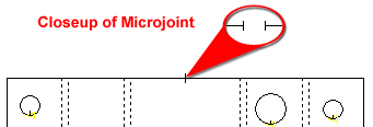
A microjoint, or bridge microjoint, is similar to a tab, but it can be placed anywhere on the perimeter of a part or pattern cutout on the part. This option defines the default size for microjoints that are placed on a pattern. To have the system auto-place microjoints see the Cutting Microjoints panel.
This option defines the default size for any corner features (radius corners, tab corners, loop corners) that you manually place on a pattern.
To create a protective border or zone around parts that will prevent overlapping during nesting on the sheet, a Bump Value must be entered. The Bump Value, given in inches, must be more than 0. Clicking Save will save this Bump value with the Preferences. You can have separate bump zones for cutting and tooling, which can have separate border sizes.
If there’s no tooling information attached to the part, the program will default to using the punch bump value. (See Bump Check On in the Sheet menu for more info.)
![]()
The Arrow Size option allows the user to specify the size for the arrows that display the direction and side of the cutting path. The range is 1 to 4. The greater the value, the larger the arrow size. Type 0 to hide the cutting side arrows, or vary the size by dragging the slider bar to the right or left, or by typing a number from 1 through 4 in the text box.
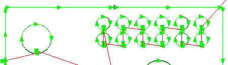
Check the Solid arrows check box, and the program will use “Solid Arrows” to show the cutting sequence direction as in the diagram.
If the Solid arrows check box remains unchecked, the program will use the default setting and display hollow arrows to show the cutting sequence direction.
Solid arrows can be used in conjunction with any of the three options below.
If Show all arrows is selected, the program shows three arrows for each line, arc or circle.
If Show the middle arrow is selected, the program shows only a single middle arrow for each pattern. This option is useful when working with small parts.
The Auto show/hide arrows option allows the program to determine how arrows display. When the user zooms in, all arrows display. When zooming out, only the middle arrows display. If the user zooms out far enough, all arrows will be hidden.