Bump Check On allows a zone or protective border to be placed around a part. This allows the user to accurately arrange parts on the sheet while preventing the parts from overlapping each other. When enabled, the part being moved during nesting will “bump” into another stationary part, but cannot be placed on top of the part.
Bump Check can only be used with the Move and Copy functions on the Sheet menu. (The Sheet>Auto Grid option will ignore the Bump Zone.) When Bump Check is enabled and one of these options is chosen, parts on the sheet will be outlined by a construction line, which indicates the Bump Zone -
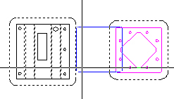
On the left is a part
without a Bump Zone
on the right is the same part after Bump Zone is enabled
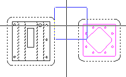
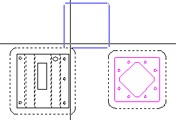
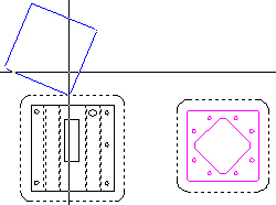
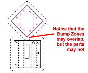
The illustration below shows that the smaller part on right is being moved and cannot cross over into the bump zone of the larger part on the left.
When moving or copying
the part is attached to the crosshair
and, when
in motion, is represented by the blue outline.
Setting the Size of the Bump Zone
The default setting of the Bump Zone is 0. To create this border around the parts on the sheet, a Bump value must be entered. The Bump Value, given in inches, must be more than 0. After the desired value has been entered, click the Save button, and the value will be saved with the Preferences. Each time the software is loaded thereafter, this value will appear. If OK is clicked, the Bump value will only be saved for the current session.
Note: Keep in mind the size of tooling that will punch between parts when you enter a bump value. In such a case, the bump zone cannot be smaller than the size of the largest tool.
For punching machines, the Bump value can be set in the Preferences > Tooling panel.
For cutting machines, the Bump Value can be set in the Preferences > Cutting panel.
Note: The Tooling panel is only available in Preferences when a punching machine is loaded. Likewise, when a cutting machine is loaded the Cutting panel is active.
For Combination machines the user will be able to use the Bump Value field in either panel. The system will need to determine if the part boundaries are being punched or cut, and then the proper Bump Value can be used. If no tools have been assigned to the part boundary, the system will default to the Bump Value located in the Punching Folder.
To enable Bump Check the program must be in Sheet view. Click on Bump Check on from the Sheet menu, or press the <F12> hotkey to toggle the Bump on and off.
Note: When the Bump Check is on, the user will only be able to select single parts, but will not be able to select a grid.
Caution! Eliminate Open Gaps in Part Geometry!
When using Bump Check On, be sure that there are no open gaps in the part geometry. This feature is very sensitive to open gaps, and will not function properly if any are present.
(See Edit > Process Geometry for information on how to eliminate open gaps in part geometry.)
Load parts manually, by going to File>Open. Be sure that Parts (*.prt) is open in the Files of type: field. Load parts by selecting a part and clicking Open. Click on Close to end the loading action and go to the work area.
The program typically stacks loaded parts into the lower left-hand corner of the sheet, and from there they must be manually (or automatically) moved into place.
Bump Check can be enabled before or after parts have been loaded onto the sheet. However, if parts have already been loaded before Bump Check is enabled, then the user must still manually separate the parts if they are stacked. Once parts are separated from each other, the Bump Zone will take effect and parts will not be allowed to overlap.