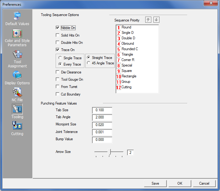
The options in the Tooling panel define the default settings for the various tooling features. You enable an option by placing a check mark in its check box. You can also type values into the text boxes to define parameters for the tooling features.
This option defines the default value for nibbling. When you enable this option, a check mark appears next to Nibble On in the Tool menu. The system automatically nibbles patterns that require more than one hit. If you remove the check mark from Nibble On, the default is set to nibble off and the system only assigns tools to single-hit patterns.
Solid Hits On
This option controls whether tool hits appear in solid or outline form. When you enable this option, a check mark appears next to Solid Hits in the Punch Sequence menu and the tool hits appear solid when you view them. If you disable the “Solid Hits On” option, then a check mark appears next to Outline Hits in the Punch Sequence menu and the tool hits appear as outlines. |
|
|
|
|
|
|
||
Outline Hits |
Solid Hits |
|
Double Hits On
This option controls whether double hits for line patterns at the same angle are checked and removed, or ignored. If you enable Double Hits On, then a check mark appears next to Double Hits On in the Punch Sequence menu. The system allows double hits and does not check for double hits on line patterns at the same angle.
If you disable the option, then the check mark is removed from Double Hits On in the Punch Sequence menu. The system checks for double hits on the line patterns at the same angle and removes them.
Note: Remember that you cannot see the removal of the double hits during sequencing. You can only see the removal of double hits while you are viewing a sequence or generating code.
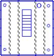
For a punching system, Trace On allows the user to view the movement of the machine punch head between punches. A line travels from one punch location to the next, indicating the travel of the machine and if the option is enabled, the trace line displays. Trace lines do not punch, but only indicate the travel path the machine moves in between hits.
Note: This option works with both Punching and Cutting machines.
By default Every Trace displays the trace line for every move in the sequence. If there are many patterns that cause a great deal of clutter, try selecting the Single Trace option, which will display only the trace line for the last pattern sequenced.
The user may also select between Straight Trace Line (default) and 45° Angle Trace Line, which gives a more accurate indication of the actual punch head movement.
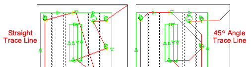
45°
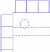
Trace line can be used to show possible collisions,
such as when the head passes near sheet clamps
A trace line may also be edited (by clicking and dragging a segment) by selecting the Sequence Features>Sequence Settings>Edit Trace Line option.
Die Clearance
Die Clearance defines the value used for Die Clearance in the Tool menu. When you enable Die Clearance, the tool assignment features check the die clearances specified by the Tool Inventory before assigning each tool. If you disable Die Clearance, the tool assignment features ignore the die clearances.
Note: Use the Tool Assignment panel in the Preferences window to define a Die Clearance Factor (%), Die Tolerance (+) and Die Tolerance (-). (See Preferences.)
Tool Gouge On
Tool Gouge On highlights areas of a part or sheet where tools overlap the lines that compose the periphery of the part. If you enable the option, any tools that overlap the periphery of the part are highlighted where Tool Gouge occurs. The areas highlight only when they are first tooled.
From Turret
When the program is assigning tools (using the Auto-Select feature) it will choose tools from the turret.
Cut Boundary
Check this box to allow software to assign laser cutting to the entire outer loop or profile.
Note: This checkbox is available only when a Combo machine is in use.
Note: Cutting (shown above as Priority 12) is available only for a combination machine. |
The Sequence Priority list allows you to define the priority of the tool sequencing when you are punching using the Auto Sequence option. The tool shapes and groups supported by the system appear in the window. A priority number appears next to each tool shape. You can modify the priority of each tool by selecting it and then clicking the Up Arrow and Down Arrow buttons. No two tools can have the same priority number. Double-click on any number to disable the option and send it to the bottom of the priority list. In the image below Rounded C has been disabled.
For info on saving tool sequence priorities for individual tools in a machine file, see Turret Window>Priority. For info on changing tool sequence priorities on the fly, see Sequence Features>Tool Sequence Priority window.
|
Tab Size
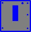
Tabs function like microjoints, but they can be applied only to the ends of a part perimeter or pattern cutout. This option allows the user to specify a default value for cutting tabs. A positive tab shortens the cutting path (notice the uncut section in black), while a negative tab lengthens the path. After clicking the icon, enter a value in the Tab Size panel and then click on the line that is to be shortened or lengthened. To clearly see the effect, sequence the part. For more info see Tabs and Tab Angles.
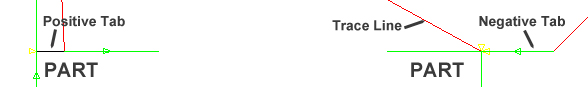
Tab sizes have been exaggerated for effect
Like regular Tabs, this option allows tabs to be placed on arcs. Enter the angle size. See Tabs and Tab Angles.
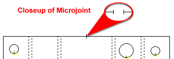
A microjoint, or bridge microjoint, is similar to a tab, but it can be placed anywhere on the perimeter of a part or pattern cutout on the part. This option defines the default size for microjoints that are placed on a pattern. To manually apply microjoints to parts on a sheet, go to Sequence Features>Punch Features>Punch Microjoint Options. To have the system auto-place microjoints see the Punching Microjoints panel.
This specifies the distance of gaps that can be ignored when geometry is processed for a punching system. The software uses the value while processing collinear lines and line sides for imported parts. (See Process Geometry in Editing Patterns.)
To create a protective border or zone around parts that will prevent overlapping during nesting on the sheet, a Bump Value must be entered. The Bump Value, given in inches, must be more than 0. Clicking Save will save this Bump value with the Preferences. You can have separate bump zones for cutting and tooling, which can have separate border sizes.
If there’s no tooling information attached to the part, the program will default to using the punch bump value. (See Bump Check On in the Sheet menu for more info.)
Arrow Size
![]()
The Arrow Size option allows you to specify the size for the arrows that display the direction of the punching path. The range is 1 to 4. The greater the value, the larger the arrow size. You can type 0 to hide the punching side arrows. You can vary the size by dragging the slider bar to the right or left, or by typing a number from 1 through 4 in the text box.