
|
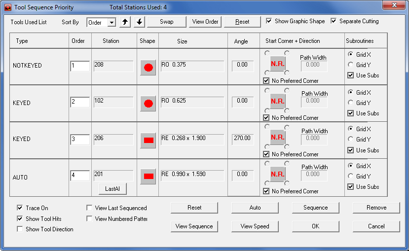
The Tool Sequence Priority window displays basic info on tools being used in a project, and contains edit tooling features such as Order, Start Corner and Subroutines. Sheet sequencing and various display options to be can also be controlled. Changes made here to tool order (priority) will be passed on to the sequence on the sheet on a per-session basis. Tool Priority set by the user in the Turret Window will not be affected by these temporary changes. | |
| The Tool Sequence Priority window floats independently over the CADCAM program while the user works simultaneously in both the CADCAM program and the Priority window. |
Sort By
|
There are four options on the drop-down menu: Order, Station Size, Tool Station and Tool Type. Click the Sort By arrow and select an option to sort the list by the order, station size, tool station number and tool type respectively. |
|
Up / Down buttons |
Select a tool row or group information and click the button to move it up (higher priority) or down (lower priority) in the order. |
|
Swap |
Switch the sequence order of two selected tools or groups. Use <Shift> + Click or <Control> + Click to select two tools or groups and then click Swap to switch the order. |
|
View Order |
Click to open a mini-window showing the original order of the tools. |
|
Reset |
Click to restore the default (original) tool order. |
|
Show Graphic Shape |
This is a toggle switch; with it the user can turn the tool shapes ON/OFF in the Shape column. |
|
Separate Cutting |
When Separate Cutting is enabled, Order #4 will be separated into Cutting Inside and Cutting Perimeter Types. This allows all the inside cutting profiles to be cut first separately and then the machine will go back and cut all of the outside perimeters to finish the job. Note: The Separate Cutting option will not display if the part is not tooled for cutting, or if a punch machine is in use. See Cutting Inside and CUTTING PERIMETER in the Tool Sequence Priority List for more information. |
|
|
|
|
Column Headers |
Description |
|
Type |
This is a static field. It displays the following station types: KEYED The slot locks in the angle of the tool key at a certain degree, such as 0° or 90°. NOTKEYED The tool floats freely in the hole. (Round tools are typically placed in these stations.) AUTO (Auto Index) The tool is typically inserted at 0° or 90° and the station is able to rotate to punch a 360° range based upon the Gcode. CUTTING With a combination machine the user can choose a cutting order inside the priority. |
|
Order |
This is the sequencing order of the tools. Modify the order in which each tool or group is sequenced by entering a value in the text box. |
|
Station |
This is a static field. It displays the station number assigned by the turret or station layout. |
|
Shape |
This is a static field. It displays the tool shape. Toggle the display by using the Show Graphic Shape option. |
|
Size |
This is a static field. It displays the tool name and size. |
|
Angle |
This is a static field. It displays the angle of the tool. |
|
Start Corner + Direction |
The options within this section allow the user to specify the starting corner and sequence direction for each tool. |
|
Click the Sequence Direction indicator graphic to toggle through the various sequence direction options. |
||
|
No Restriction. The system will sequence the tool (path) using the shortest distance from the last pattern sequenced. |
|
|
X-Axis. Sequence the tool (path) in the X direction before moving along the Y-axis. |
|
|
Y-Axis. Sequence the tool (path) in the Y direction before moving along the X-axis. |
|
|
Line-By-Line X. Sequence the tool (path) along the primary X-axis, return to the original starting edge, and then sequence the tool along the closest pattern off the primary axis from the last sequenced pattern. |
|
|
Line-By-Line Y. Sequence the tool (path) along the primary Y-axis, return to the original starting edge, and then sequence the tool along the closest pattern off the primary axis from the last sequenced pattern. |
|
No Restriction |
No Restriction. If there is a check mark in the No Restriction check box, the system uses the shortest path when sequencing the tool. If the check mark is removed, the Starting Corner options become available. |
|
Starting Corner |
Select one of the four Starting Corner option buttons that surround the Sequence Direction indicator graphic to determine where the sequencing begins. Remove the check mark from the No Preferred Corner check box to activate. |
|
|
Top Left. The sequencing for the tool will begin in the upper left corner of the sheet. |
|
|
Top Right. The sequencing for the tool will begin in the upper right corner of the sheet. |
|
|
Bottom Left. The sequencing for the tool will begin in the bottom left corner of the sheet. |
|
|
Bottom Right. The sequencing for the tool will begin in the bottom right corner of the sheet. |
|
Path Width |
If the Path Width text box is available, the sequencing for the tool would reflect the Line-By-Line method, except that the sequence would not return to the same edge of the sheet as the first pattern selected. It can deviate off the primary axis (X or Y). The value in the Path Width text box specifies a width of a hallway variation for moving off the primary axis. For more info see Sequence Information Panel>Sequence Direction. |
|
Subroutines |
Use the options in this section to specify the generation of subroutines for the tools or groups. |
|
Use Subs |
Place a check mark in the Use Subs check box for a corresponding tool or group to generate subroutines. If Use Subroutines is enabled for a tool or group, the Grid X and Grid Y options also become available. |
|
Grid X |
Select Grid X for a corresponding tool or group to sequence the subroutine along the horizontal axis. |
|
Grid Y |
Select Grid Y for a corresponding tool or group to sequence the subroutine along the vertical axis. |
|
Last AI |
This option is only available if the last or only tool in the Tool Sequence window is an Auto-Index (AUTO) station tool. Click the Last AI button to open the Last Used Auto Index Angle dialog, which allows the user to modify the travel direction, last index angle and start corner of the last auto-index tool used in the sequence. |
|
Check boxes |
Options in this section give the user more control over work area display. |
|
Trace On |
This option controls the lines that appear from hit to hit. When checked ON the lines will appear, but when checked OFF the lines will not appear. This is similar to the Trace On option in the Preferences>Tooling window. |
|
Show Tool Hits |
Check this ON to show tool hits on the part geometry in the work area. This is similar to the Show Tool Hits option in the Preferences>Display Options window. |
|
Show Tool Direction |
Check this ON to show the tool direction on the trace lines. This is similar to the Show Tool Direction option in the Preferences>Display Options window. |
|
View Last Sequenced |
Check this ON to highlight the last pattern that was sequenced. This will help the user to be able to see where they left off in the sequence. This is similar to the View Last Sequenced option on the Punch Sequence>View-Tool Hits, View Last Sequenced page. |
|
View Numbered Patterns |
Check this ON to have the system output numbers for each pattern sequenced. The numbers will appear in the NC Program before the code for the corresponding pattern. Note: To be sure that the sequence numbers are visible in the work area, it may be necessary to select a darker color for the Tool Gouge/Cut Attr./Seq.# item. See Color and Style Parameters>Set Color for more info. This is similar to the View Numbered Patterns option in the Preferences>Display Options window. |
|
|
|
|
Function Buttons |
Options in this section give the user more control over sequencing. |
|
Reset |
Hit the Reset button to start the sequence over from within the Priority window. When clicked the system requires the user to agree to resetting the sequence. This is similar to the Reset function in both the Punching Sequence and Cutting Sequence menus. |
|
View Sequence |
Hit View Sequence to display the sequence from start to finish using the current viewing speed. This is the standard View Sequence feature found in both the Punching Sequence and Cutting Sequence tabs. |
|
Auto |
This button auto sequences the sheet. After changes have been made in the Tool Sequence Priority window the user may run Auto sequence from inside this window. This is the standard Auto Sequence option found in both the Punching Sequence and Cutting Sequence tabs. |
|
View Speed |
Set the sequence viewing speed. In the Viewing Speed dialog that appears enter a viewing speed and then click OK. |
|
Sequence |
With this option the user may make changes to a tool (or tools) and view the sequence for just that tool. Select a tool (or tools using ctrl+click) and red box will appear around the tool(s). Click the Sequence button to view the sequence for the selected tool(s). |
|
Remove |
Click Remove to remove a selected tool or tools from the sequence. Before this button can be used a tool or tools must be selected and the sequence for these tools must already be generated. |
|
OK / Cancel |
Click OK to save the changes and to exit the window, or click Cancel to exit the window without saving. |
|


