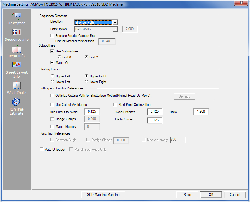
The Sequence Information panel allows you to specify the Auto Sequence parameters. The system uses this information when auto-sequencing a sheet.
Option |
Description |
|
|
Use the options in this section to specify the sequence direction settings. |
||
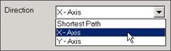
Direction |
Select one of three directions from the drop-down list.
Shortest Path The system will sequence each pattern using the shortest distance from the previously sequenced pattern. X-Axis The system will sequence the patterns along the X or horizontal axis. Y-Axis The system will sequence the patterns along the Y or vertical axis. |
|
Path Option |
If X-Axis or Y-Axis is selected, the Path Option drop-down list and text box become available. There are two options on the drop-down list: Line-By-Line and Path Width.
|
|
|
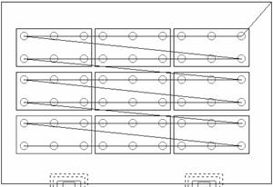
Note: When you select Line-By-Line, all of the patterns in line on the primary axis are sequenced, and then upon returning to the original starting edge, the closest pattern off of the primary axis from the last pattern is sequenced, etc. If you select Path Width, the sequencing would reflect the Line-By-Line method, except the sequence would not return to the same edge of the sheet as the first pattern selected. It can deviate off the primary axis (X or Y). The value in the Path Width text box specifies the width of a hallway variation for moving off the primary axis. If the path width value is zero (0), the sequence path moves along the primary axis only, until all the patterns are sequenced and the table changes direction. See the illustration below. |
|
|
|
|
|
Auto Sequence with X-Axis and Line-By-Line |
|
|
Note: You can apply these settings on a tool-by-tool basis for punching machines or globally to the sheet. (See Tool Assignment.) |
|
|
The first pattern establishes the location of the Path Width. If the Path Width is zero (0), the system sequences all the patterns along the primary axis (X or Y) and then moves off the primary axis to the next closest pattern. It then changes direction and continues until all the patterns are sequenced. The direction moves away from the starting corner, in the direction set on the tool, or the default system setting. |
|
|
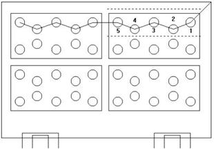
A hallway is defined if the Path Width has a value other than zero (0). The travel can then deviate off the primary axis by the specified amount. However, the sequence cannot change direction before all the patterns along the primary axis have been sequenced. If a pattern partially occupies a hallway, the pattern is completely sequenced. The system returns to the next closest pattern in the hallway. See the illustration below. |
|
|
|
|
|
Path Width indicated by dashed lines. A subroutine sequences patterns 1 through 5 across the sheet.
|
|
|
Process Smaller Cutouts First Typically, if a large cutout is cut first it may weaken the material and cause deformation, while smaller cutouts will generally not have this effect. Checking this box ON allows the program to make the calculations necessary to process smaller cutouts first and larger cutouts afterward. This option is especially helpful when cutting thin material that has small and large cutouts. Set the value for the thickness of the material in the First for Material thinner than text field. The system will ignore any materials thicker than this setting.
|
|
|
Use the options in this section to define your subroutine settings. |
||
Use Subroutines |
If you enable this option, Auto Sequencing outputs subroutine programs for parts that are gridded on the sheet (your machine driver must support subroutines). Grid X is the default setting unless you modify it. Grid X indicates that parts in the grid will be sequenced horizontally across the sheet. Grid Y indicates that the parts in the grid will be sequenced vertically across the sheet. You can also change the direction for each tool in the Sequence Order. Automatic sequences use this as the default direction. If Shortest Path is selected for the Sequence Direction, auto sequencing will sequence in the X direction. If X-Axis or Y-Axis is selected, the auto sequence will output subroutines, but row-by-row, always starting at the same end of the row. |
|
Grid X/Y |
||
|
||
Macro On |
This option controls the default for whether macros are used within Start Subroutines. While the setting in the Sequence Info page is the default, you can define this option on a sheet-by-sheet basis using the Macro On sequence feature (Sequence Features/Sequence Settings). If the check box in the Sequence Info panel has a check mark, the Macro On option is selected on the Sequence Settings submenu. Select the option from the menu to toggle macros on or off for the current sheet only. |
|
Starting Corner |
The Starting Corner options define the starting corner used by Auto Sequence. Upper Right is the default corner, but you can also define Upper Left, Lower Left and Lower Right. Some machines have the 0,0 origin defined at a different corner other than the default system setting. This allows Auto Sequence to start from any corner on the sheet. |
|
|
||
|
||
|
Use these options to define the cutting preferences and the parameters for cutout or feature avoidance.
|
||
Optimize Cutting Path Settings for Shutterless Motion |
This option allows the user to control parameters when optimizing the cutting path and using Auto Sequence. Check ON the checkbox to activate the Settings button. Click for more Optimize Cutting Path info.
|
|
Use Cutout Avoidance |
Place a check mark in the check box to implement cutout avoidance. Auto Sequence avoids any cutouts in a part by adjusting the start points so that the cutting head never crosses them. If you enable the option, the software avoids any cutout that exceeds the value you type in the Minimum Cutout to Avoid text box. The system will lift the cutting head before crossing over a cutout. If you remove the check mark and disable the option, the system passes over any previously cut paths without checking. (See Cutout Avoid On in Cut Sequence Settings for more information on this feature.) |
|
|
Notes: |
|
|
1. The software does not avoid cutouts that contain microjoints or tabs. The system crosses over any continuous path that contains one or more microjoints or tabs. Since the microjoints or tabs hold the slugs in place, the software does not need to avoid the cutouts. The same rule applies to cutouts that are undercut or overcut. |
|
|
2. When using cutout avoidance during sequencing, it is strongly recommended that you sequence in Part mode (Part View) before proceeding to Sheet mode (Sheet View) to continue part sequencing. This is due to the pattern processing that occurs when switching between Part and Sheet view. It is never a good practice to switch between modes while implementing cutout avoidance. |
|
|
3. Cutout Avoidance with Macro Memory enabled may result in extra moves during Auto or manual sequencing. The cutting head will make some moves that could cross over the cutout(s). |
|
|
4. If the Macro options are enabled for patterns in the material file, and Cutout Avoidance enabled for the machine, the system removes the lead-outs from the cutting path to prevent the head from dropping into the hole after cutting it. |
|
|
5. When auto-sequencing grouped patterns (grids/lines), the system explodes the group to allow for cutout avoidance. However, if you manually assign the sequence, the system will not explode the grouped patterns, thereby causing cutout avoidance to travel over the cutouts. |
|
Min Cutout to Avoid |
The value you type in this text box defines the limit for feature avoidance. If the system encounters a shape that is less than the specified value, it allows the cutting head to travel over the shape. If a shape is greater than the avoid value, the system directs the cutting head around the cutout. |
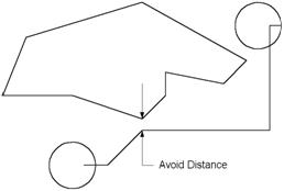
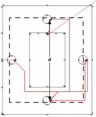
Avoid Distance |
The value typed in this text box defines the distance of the cutting head from the actual cutout. The laser head will not travel any closer than the specified value. In the illustration below, the system cuts the bottom hole, and then moves toward the upper hole, avoiding the cutout in the center. The system calculates the head movement using a 45o angle to determine the location of any surrounding patterns. If it detects a cutout, then it moves the head in the X-axis or Y-axis to avoid the shape. Notice that the head went as far as possible before moving in the X-axis. The system continued along the X-axis until it aligned with the next hole and traveled along the Y-axis to cut it. |
|
|
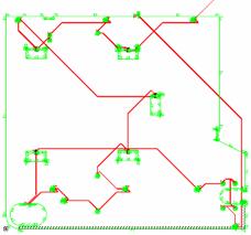
Ratio |
The value you type in the Ratio text box is actually a factor amount derived from the distance (d) between the start and end points. The system calculates the movement from the previous cut pattern to the next cut pattern and generates a Calculation Perimeter. The Calculation Perimeter is dynamic; the system derives the area from pierce point to pierce point. The system determines whether there are any cutouts to avoid within the perimeter while the machine head traverses the sheet, thereby reducing the sequencing time. The larger the Ratio value, the greater the area of the Calculation Perimeter (as indicated by the dashed line in the illustration below). The bold lines in the illustration represent head down movement, while the thinner lines represent head-up movement.
|
Dodge Clamps |
Enable this option to avoid the work clamps while sequencing. Type the distance required to avoid the work clamps in the text box. The distance value is added to the Y dead zone. |
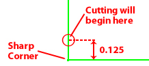
Distance to Corner |
When a laser begins cutting on a new pattern, it will typically begin on a sharp corner, such as the corner of a Rectangle. This could possibly damage the material by overheating. Avoid such a sharp corner by entering a distance value, which will move the start point. Start Point Optimization must be checked ON to use this option.
|
Macro Memory |
This option allows you to specify the maximum memory limit for a machine when using G98-type programming. Some machine controls can only manage so much code in a macro statement (U1-V1). Some controls can process up to 2,700 characters, while others can process up to 3,000. The software compares the value in the Macro Memory field with the number of characters being generated. If Use Subroutines and Macro On are enabled during Auto Sequence, the software closes the grid and outputs the proper code, resets the character count, and then starts a new macro. |
|
Note: If you sequence the sheet manually, and exceed the Macro Memory value, the system prompts you to select either Grid X or Grid Y to continue. The software then closes the macro and duplicates it across the sheet. You can then continue to manually sequence the sheet. |
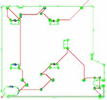
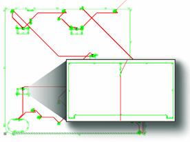
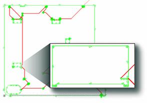
By default the program uses a snap point as the starting point in a cutting sequence, but this is not always the closest starting point. Check the Start Point Optimization checkbox to allow the program to begin cutting on the closest point on the next cutting pattern instead of the closest snap point. Instead of using the preset start point in the part, the system calculates the new start point of the current cutting path based on the location of the next cutting path in the part. To enable this function the Start Point Optimization checkbox must be checked, and Cutout Avoid On in the Cut Sequence menu must also be enabled. See also Optimize Start Points in Cut Sequence. |
|
|
Cutting Path before enabling |
Cutting Path after enabling |
|
|
Close-up of cutout before |
Close-up of new start point on cutout |
Punching Preferences Use the options in this section to define the punching preferences. |
|
Common Angle |
This option determines whether the Common Angle option in the Punch Sequence menu is active or inactive. When enabled, Auto Sequencing looks for patterns using the same tool and angle as the one just sequenced. |
Dodge Clamps |
Place a check mark in this check box to avoid the work clamps while sequencing. Type the distance required to avoid the work clamps in the text box. The distance value is added to the Y dead zone. |
Macro Memory |
This option allows you to specify the maximum memory limit for a machine when using G98 type programming. Some machine controls can only manage so much code in a macro statement (U1-V1). Some controls can process up to 2,700 characters, while others can process up to 3,000 characters. The software compares the value in the Macro Memory field with the number of generated characters. If Use Subroutines and Macro On are enabled during Auto Sequence, the software closes the grid and outputs the proper code, resets the character count, and then starts a new macro. |
|
Notes: If you are sequencing the sheet manually, and exceed the Macro Memory value, the system displays a warning, and prompts you to select either Grid X or Grid Y to continue. The system closes the macro and duplicates it across the sheet. You can then continue to manually sequence the sheet. |
Auto Unloader |
To allow the program to show the part unloading process as soon as the sheet is sequenced in Cut Sequence or Punch Sequence, check this option. |
| SDD Machine Mapping | Clicking this button links the current machine in AP100US to a Machine registered in SDDJ. Data from the programs that have been stored into SDDJ can be linked to other products that link to SDDJ (such as AP100G CAM or Dr.ABE_Blank). Contact Sales Support to learn how to activate the SDDJ Server. Click for complete SDD information. |
Save / OK / Cancel |
Clicking Save after making changes will save those changes as the default. Click OK to save changes only for this session (system reverts to default settings when program is closed). Click Cancel to cancel any changes and close the window. |