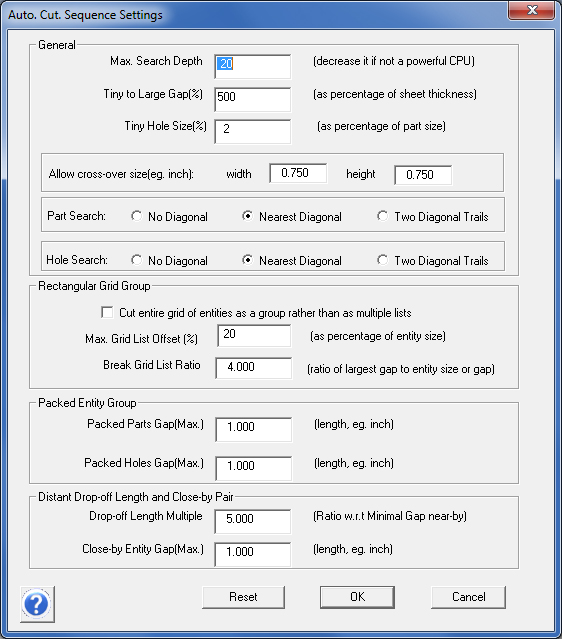
Options here allow the user to control parameters by entering values when optimizing the cutting path. See the explanations below.
.
General
Max Search Depth: This value represents the search depth that the program will search through to find a solution for an optimized cutting time before issuing a warning for excessive CPU usage. Increasing the value requires a more intensive use of system resources, which increases overall time. The search increases exponentially (as does usage of system resources) for each value point entered by the user. Values entered may range from 10 to 30.
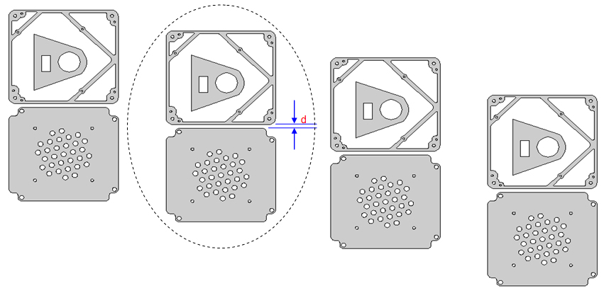
Tiny vs Large Gap (%): This is the distance between small geometries, such as a small hole versus a near-by large geometry hole on the same part ("d" value in the image below). A higher percentage value means better cutting quality for small holes, which are adjacent to a large hole. Values entered may range from 10 to 1000, and are given in a percentage with respect to the thickness of the sheet.
Note: If "d" divided by the thickness is less than this value and the area of the large hole divided by the area of the small hole is less than the square of this value, then the small hole is considered to be too close to be cut after the large hole; that is, the small hole should be cut before the large hole.
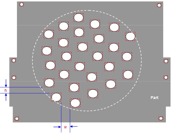
Tiny Hole Size (%): This is the size of a hole with respect to overall part size, given in a percentage and considered in the x and y directions. The program considers a hole as "tiny" based on the user-entered value. Any hole larger in size than the user-entered value will be not considered as a tiny hole. Tiny holes will be handled with extra consideration by the program, such as cutting them before large holes. Values entered may range from 0 to 99. In image #1, all round holes are considered "tiny" but the square and oblong are not.
Allow cross-over size - Enter width and length values in inches for a hole. This will allow the laser head to cross-over (ignore) any hole smaller than the size given without a problem.
Part Search and Hole Search allow the program to search in a diagonal direction for the next cutting item.
Part Search
No Diagonal - The search direction will be limited to either a horizontal or vertical search with respect to the current position. No diagonal search will be considered.
Nearest Diagonal - The search direction will be extended to the nearest diagonal part with respect to the current position.
Two Diagonal Trails - The search direction will first be extended to the nearest diagonal part and then extended to an additional diagonal direction with respect to the current position.
Note: Values are in inches. Width and Height default values are 0.750. Part Search permits a search range of 0 - 1 inch.
Hole Search
No Diagonal - The search direction will be limited to either a horizontal or vertical search with respect to the current position. No diagonal search will be considered.
Nearest Diagonal - The search direction will be extended to the nearest diagonal hole with respect to the current position.
Two Diagonal Trails - The search direction will first be extended to the nearest diagonal hole and then extended to an additional diagonal direction with respect to the current position.
Note: Values are in inches. Width and Height default values are 0.750. Hole Search permits a search range of 0 - 1 inch.
Rectangular Grid Group
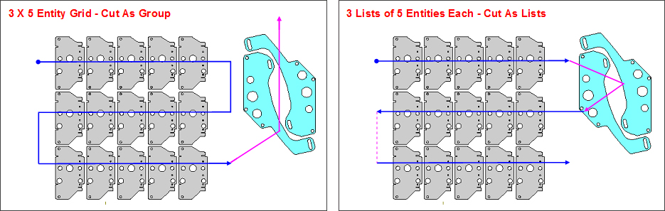
Cut entire grid of entities as a rectangular group, rather than as multiple lists: A group of parts with the same geometry can be packed (or grouped) to be cut as a single entity. The image at left shows the cutting result with this option checked ON. The smaller gray parts are cut first, then the larger aqua parts are cut.
If the option is NOT selected, the smaller and larger parts will be cut in a normally sequenced row as shown in the image at right.
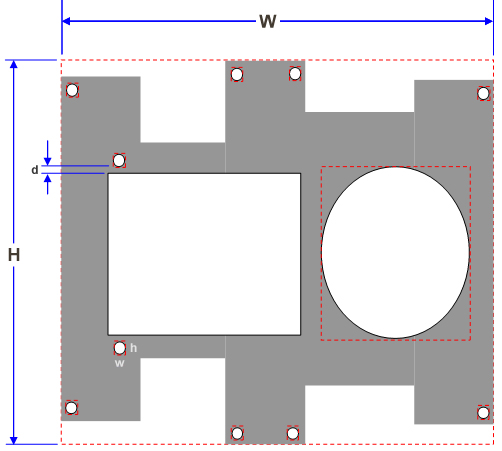
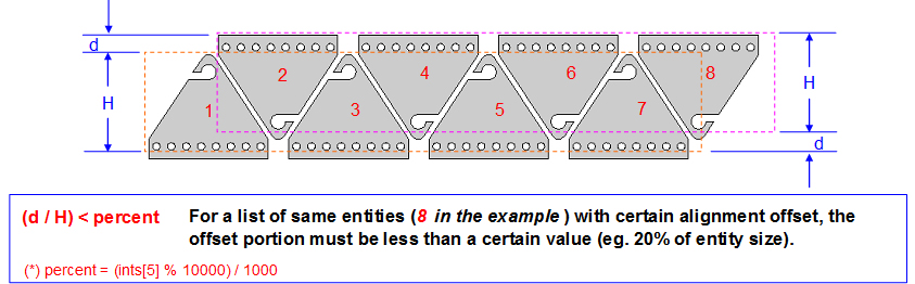
Max. Grid List Offset (%): Enter a value for the percentage of the offset portion (d), which is a percentage of the part size (H). For example, if a value of 20% is entered, the width of the offset portion of the part must be less than 20% of the part size in H. This will combine the parts as a single list and be cut accordingly. However, if d over H is greater than 20%, the parts will be separated into two lists.
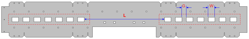
Break Grid List Ratio: Use this option for a list of identical holes or parts in a horizontal or vertical orientation. To begin with, the program sees the two lists (areas outlined in red in image #5) as one single list because they are in a perfect line up and will cut them accordingly.
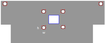
If the ratios of L to G and L to W are greater than 4.0 (the default value), then the program will divide the original single list into two lists. L is the largest gap between two neighboring holes. G gap is the smallest gap and W is the object width. The same evaluation will also be made for a vertical list of identical holes or parts. Values entered may range from 2.1" to 10.0".
Note: A single list is treated as a group.
Packed Entity Group
Packed Parts Gap (Max): A group of parts with the same geometry can be packed (or grouped) as a single cutting entity. The program will check horizontal and vertical distances (or gaps) between neighboring parts to determine if the parts qualify as "packed." (A pack contains three or more parts.) Any group of parts having a size lower than or equal to the user-entered value will be considered to be cut as group. Values entered may range from 0.1" to 20.0".
Packed Holes Gap (Max): A group of holes with the same geometry could be packed (or grouped) as a single cutting entity. The program will check horizontal and vertical distances (or gaps) between neighboring holes to determine if the holes qualify as "packed." (A pack is more than three holes.) Any group of holes having a size lower than or equal to the user-entered value will be considered to be cut as group. Values entered may range from 0.1" to 20.0".
Distant Drop-off Length and Close-by Pair
Drop-off Length Multiple: This field allows the user to set the maximum search distance for neighboring relationship setups among entities in a horizontal / vertical direction, versus a diagonal direction. The value is based on the gap between horizontal or vertical neighbors (gap #D in the image), versus the gap between diagonal neighbors. If the user enters a value of <5>, then geometries further than 5 times the gap size in D can be bypassed by the system (distance drop-off). Values entered may range from 2.0 to 10.0.
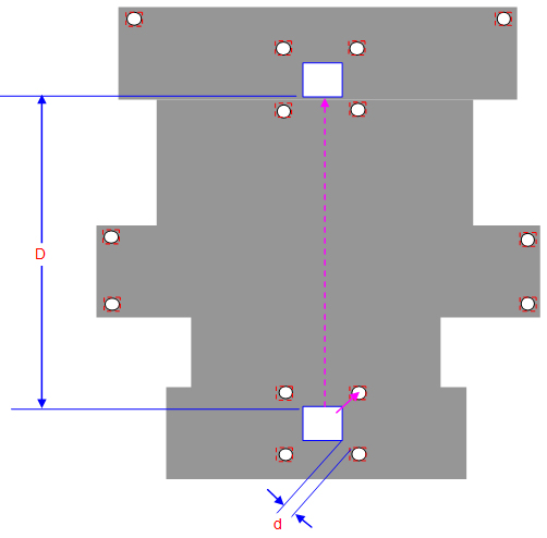
Close-by Entity Gap (Max): If two different (but basically similar in outer parameter size), neighboring geometries are within the range set by the user ("d" in the image), then these two geometries may be cut as a group. The two parts circled will be treated by the system as one group. Values entered may range from 0.1" to 2.0".