![]() This
option rotates a part around its origin.
This
option rotates a part around its origin.
Notes: The system rotates the part on the sheet only. The rotation does not affect the design file.
When you rotate a part with tools, rounds, squares at angles divisible by 90, and auto-index station tools, remain assigned to the part. See other options for retaining tooling when rotating parts.
The part origin remains constant, no matter what the angle of rotation.
You can also rotate an entire grid of parts by rotating one of the parts in the grid. Unless you are rotating a square part, you must specify new X and Y spacing values.
Usually when you rotate the part, the bottom left corner remains as the left edge (the part offset). However, if you rotate the part with Show Actual Part Boundary active, the part rotates around the point you specified and the part offset changes. To rotate the part and maintain the part offset, make sure to disable Show Actual Part Boundary. Modifying the part angle in SHEET View maintains the offset when Show Actual Part Boundary is active.
Select Rotate on the Sheet tab and move into the work area. Click the part you want to rotate. The part outline box begins to move with the pointer. The system prompts you for the new angle.
Rotate the part by dragging the mouse until the angle in the Part Properties window or is correct and then left-click to finalize. Edit the angle by manually entering a value in the Angle text field.
Retaining Tooling when Rotating Parts
To avoid dropping tooling from a part due to a change in part angle, when a part is selected to be rotated the system will display an alert dialog that allows the user to select which tooling to retain.
Note: This option is available in SHEET mode only and must be applied to parts on an individual basis.
 |
Notice
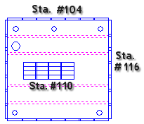
that in the above part in its original position it is punched
out by the tool in Station #110 in the center cutout, Station
#104 in the Y, and Station #206 in the X.
|
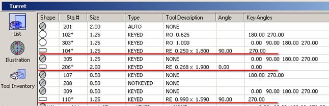
Stations #104, 206 and 110 contain RE tools that will be rotated
In the Turret>List window above, notice the Angles and Key Angles for Stations 104, 206 and 110. Key Angles of 270 exist for Stations 104 and 110, whereas Station 206 has a key angle of 0.
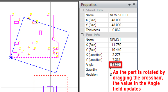
Rotate the Part
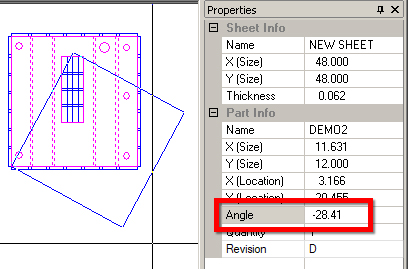
Select Rotate from the Sheet menu, left-click the part and drag it around its point of origin. Notice that the Angle field (highlighted in red) updates as the part is rotated. Left-click to place the part, or manually enter a value in the Angle field, hit <Enter> on the keyboard and the system opens the alert dialog shown here -
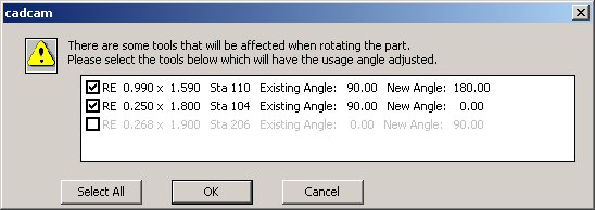
The results in this dialog were obtained when the part was rotated 90 degrees
In the Alert dialog the system lists the tools that must be rotated to meet the rotation requirement of 90 degrees.
Because Stations 110 and 104 have the necessary angles and/or key angles, they are listed in bold-face print as they can freely rotate to the new angle.
Station 206 is grayed out because it doesn't have the necessary angle or key angle. If the user places checks in the check boxes for the first two stations (as in the image above) and then clicks OK, the tooling in Station 206 will be dropped by the system.
To punch out this part the user must open the Turret List window and either find a new station with the proper key angles for the RE 0.268 x 1.900 tool, or add a new tool from the tool inventory to a station with such key angles.
In the above dialog, the user can click Cancel, choose Undo from the menu to reverse the rotation (if necessary) and open the Turret>List window to make changes to the tool and/or station.
Note: Tools that are not affected by rotation (such as rounds and AUTO station tools) never appear in the list.
The RE 0.268 x 1.900 tool, previously in station #206, has been moved to station #116, which has the needed key angle. The part is again rotated, which opens the alert dialog -
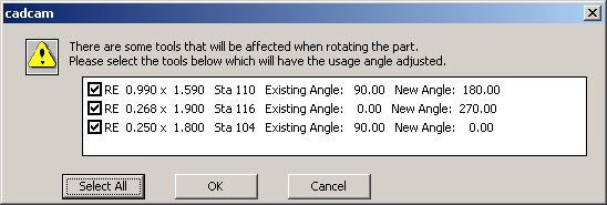
All tools appear in bold face and can now be rotated. Click the Select All button to place checks in all the boxes and then click OK.
|
|
In the image to the left, notice how the tools in Stations #104, #116 and #110 have rotated. Compare this to the original tooling configuration in the above image. |
Rotating Multiple Parts
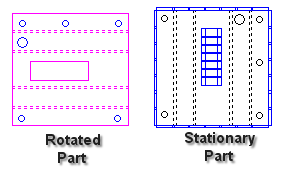
A conflict can occur between two or more parts that share the same tooling assignments. The part on the left was rotated, but the tooling was dropped; however, the stationary part has retained the original tooling, as the system did not allow the tools to rotate. Tools that are shared by different parts on a sheet and will be dropped are grayed out in the alert dialog tooling list.