![]() The Auto
Grid option allows the parameters for creating a part grid to be specified
by typing values in the Auto Grid Properties Window. The values specified
are used to duplicate the active part in the X and Y direction and the
software derives the best solution from these values for maximum sheet
utilization.
The Auto
Grid option allows the parameters for creating a part grid to be specified
by typing values in the Auto Grid Properties Window. The values specified
are used to duplicate the active part in the X and Y direction and the
software derives the best solution from these values for maximum sheet
utilization.
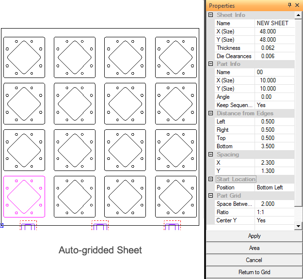
Select Auto Grid from the Sheet menu. The user may enter/edit values in the Auto Grid Properties window before, during or after the sheet has been gridded by clicking the Apply button. Edit values again as needed and click Apply again until results are satisfactory.
Option |
Description |
Sheet Information |
|
Name |
The file name of the sheet. |
X (Size) |
The X dimension of the sheet. |
Y (Size) |
The Y dimension of the sheet. |
Thickness |
The thickness of the material. |
Die Clearance |
This is the Die Clearance that was assigned to the tool. If more than one Die Clearance was assigned, the user may select a different Clearance by clicking in the field and selecting a different die from the pull-down menu. See ATC - Select Die Clearance for more info. |
Part Information |
|
Name |
The file name of the part. |
X (Size) |
The X dimension of the part. |
Y (Size) |
The Y dimension of the part. |
Keep Sequence |
This option allows you to maintain any sequencing after you modify the grid. The option is only available if you have enabled the Subroutine options in the Sequence Info panel of the Machine Setup Window. |
Distance from Edges |
|
Left |
Type constraint values for the Left, Right, Top and Bottom edges to specify the parameters for the auto grid. |
Right |
|
Top |
|
Bottom |
|
Spacing |
|
X |
Type values for the X and Y parameters to specify the horizontal and vertical spacing for the parts in the grid. |
Y |
|
Start Location |
Select Start Location from any one of the four corners of the sheet from the pull down menu.
|
Part Grid |
The settings here are also found in the System Setting>Machine>Sheet Layout Info>Auto Grid Tab Panel. Settings in both panels are synchronized. |
Space Between |
Enter a value to control spacing between grids. |
Ratio |
Choose either 1:1 or 1:2 (large parts to small parts) to confirm the amount of parts that will be auto-added to the sheet. This ratio is called when Method D is selected in the Sheet Wizard>Settings>Sheet Layout Info section. |
Center Y |
Check ON this checkbox to allow grids to be centered in the Y. |
Apply |
Click the Apply button to complete or update the auto grid. If you change any of the values in the Distance from Edges or Spacing sections, you can click Apply to view the results. |
Area |
The Area button in the Auto Grid property window allows you to define a rectangular area for a part grid. Select the part to grid, and then specify the starting and ending corners of the rectangular area. The system then determines the best solution and fills the defined area with a part grid. Notes: The area you define for the grid must be twice the overall part size or greater. If you define an area smaller than the selected part’s overall size, the system will not create the grid. You can define the horizontal and vertical spacing by typing values in the X and Y text boxes located under Spacing in the Auto Grid property window. Create a new sheet and load a part. The part appears at the default coordinates of 0X 0Y. Select Auto Grid… from the Sheet menu. The Auto Grid property window appears. Define the spacing for the grid. Move the pointer into the property window and click X under Spacing to select it. Type 0.125 <Tab> 0.125 <Enter> to specify the horizontal and vertical spacing. Click the Area button. The system prompts you to select a part for the fill area. Move the crosshair over the part and click the left mouse button to select it. The system prompts you to select the first corner of the area. Type the coordinates or use the mouse to select the first corner. The system then prompts you to select the second corner of the area. Type the coordinates or move the crosshair in a diagonal direction to select the second corner. Click the left mouse button or press <Enter> to complete the rectangular area. The grid appears on the sheet with the spacing that you specified. |
Cancel |
Click Cancel to exit. |
Return to Grid |
Click Return to Grid to close the Auto Grid Property window and to return to the part grid. |
Notes:
If you load a machine file containing clamp settings, make sure to input a value in either the Left, Top, Bottom or Right text boxes that allows for the clamp dead zone. The SHEET View displays the clamp orientation along the left, right, top or bottom edges of the sheet.
Auto Grid will not create grids that are larger than the sheet, unless you type negative values in the Distance from Edges text boxes.
You can press <F11> in PART or SHEET View to automatically grid the part. If PART View is active, and you press <F11>, the software switches to SHEET View and grids the part.
If the software detects more one instance of a part, and/or different part(s) on the sheet, the Apply button is disabled in the Auto Grid property window. You can still click the Area button to select and grid multiple parts.