|
|
|
|
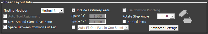
Now it is time to choose Sheet Layout, Sequence and Report settings. Click Settings and the Settings Panel appears. (While in this panel the Settings button is highlighted in purple.)
|
|
|
|
Option |
Description
|
Nesting Methods |
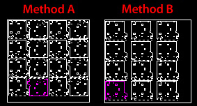
Choose Nesting Method A or B from the pull-down list. These two default options meet the requirements of most users. Choosing Method A means that the program will regard high sheet utilization as the first priority when nesting parts on a sheet. This method allows more parts to be nested on the sheet. Method B means that the program will regard Part Grid as the first priority. This allows the user to have an orderly nested sheet.
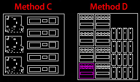
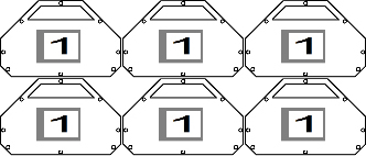
(When Method A has been selected and the Start Nesting button is clicked, the program will put the nesting operation on hold and launch the Choosing Nesting Results window. For more info see Start Nesting>Choose Nesting Results.) Note: If the Auto Fill... pull-down is checked ON these options are disabled. Methods C & D (See how to enable these options.) Method C controls nesting logic and maintains columns and rows. This feature requires the Sheet Wizard to grid the parts in order from top to bottom, left to right and then splits the sheet between part columns. When this Method is selected the Space "X" and Space "Y" fields become active allowing the distance between parts to be controlled. Choosing Method C when loading a part will fill the sheet with the part automatically and the quantity will be shown in the sheet UI. Method D Another nesting option is Method D, which differs from the other three types in that it will auto-generate a minimum number of grids (one grid per unique part) and then add an optimal number of parts giving the best sheet utilization. In the above image, the user has loaded only 2 unique parts. (With Method D selected, part Quantity in Parts List for Nesting is ignored.) Method D then placed these parts into two separate grids, and added additional parts to fill out the sheet. Typically, Method D allows for a 1:2 ratio (large to small parts). Notice that there are twice as many small parts in the image. When three or more parts are loaded, the ratio will be 1:1:1. To control the ratios used, spacing between grids and other options, see Machine>Sheet Layout Info panel>Auto Grid tab for more info. Notes:
Method D only allows part rotation to 0 or 90 degrees. For Methods C and D to appear in the Method pull-down list (along with Methods A and B), they must first be enabled. Click open the Advanced Settings window and check the option ON. |
Include Features / Leads |
This option instructs the system to evaluate the values of part features (corner features, lead-in lines, lead-out lines, etc.) while attempting to nest the parts. If this option is unchecked, the system ignores the part features while nesting and only uses the value specified for the Include Tools/Beam > Beam Diameter option. |
Use Common Punching |
For a combination machine, this option would instruct the system to use the tool width as the spacing parameter while nesting the parts. For example, if the exterior tools are 0.250, then the system nests the parts using 0.250 spacing. This option is disabled if a cutting machine is loaded. |
Auto Tool Assignment |
Use this option to determine whether the system automatically assigns tools when loading files for a nest job. Place a check mark in the check box to automatically assign tools during the nest job. This option is disabled if a cutting machine is loaded. |
Nest Around Clamp Dead Zone |
A check mark in this check box instructs the system to nest parts around the dead zones reserved for the sheet clamps. |
Space X / Y |
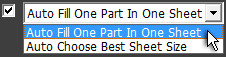
These text fields allow the user to manually enter a space value between parts on the sheet. They are enabled when Nesting Methods A and B alone appear in the Methods pull-down menu, and the Auto Fill One Part... option has been checked ON as shown here -
These options
are unavailable Auto Fill One Part in One Sheet requires the system to place a part (regardless of the quantity entered in the Parts List>Quantity column) on its own sheet and fill the sheet with that part. Using this option overrides the nesting logic of Methods A and B, filling out the sheet according to its own parameters. When selected the Space X /Y text fields are active. Note: When this option is chosen, the Quantity column in Parts List for Nesting is uneditable, because the system decides how many parts are needed to fill the sheet(s). Auto Choose Best Sheet Size allows the system to select the best sheet size for all parts being nested. When selected the Space X /Y text fields are disabled. This option works in conjunction with the nesting logic of Methods A or B, and picks from material sizes of the assigned type. Notes: With this option the user must be sure that more than one sheet is available for the Sheet Wizard to draw from, and the Multiple Sheets option in Sheet Wizard>Nesting Parameters must be enabled. With this option the Quantity column in Parts List for Nesting is editable. Using Methods C and D with Space X / Y The Space X /Y text fields are also active when Methods C or D are chosen; however, the Auto pull-down is disabled.
|
Rotate Step Angle |
Enter a value for the Rotate Step Angle. For example, if 30 is entered, then the part will rotate only to 30, 60, 90 degrees and so on. Note: The lower the number the more often the program must calculate the angle, resulting in greater accuracy. If the number is higher it will be easier for the program to nest, but it can be less accurate.
|
No Grid Parts |
This option allows you to instruct the system whether to process gridded parts as a single unit, or to ignore gridding and individually process the patterns as single parts, rather than a collection of parts.
|
Space Between Common Cut Grid |
Check the box to enable a space to be placed between grids during the common cut process. The space is the value from the Spacing field in the Layout Setting panel. This option is most applicable to Straight Edge Common Cutting. If Auto Fill One Part in One Sheet is selected, this option will be grayed out. (See Space X / Y above for info.) |
|
|
|
Show
Page After Nesting |
|
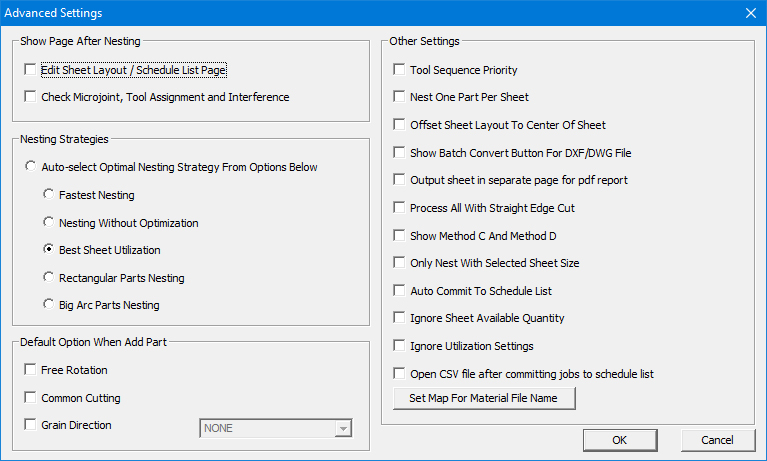
Check ON Edit
Sheet Layout / Schedule List Page to have the Edit
Layout panel and Schedule List
option display immediately after a sheet or job is nested. |
|
Check ON Check
Microjoint, Tool Assignment and Interference to have the
program run a check on these items. The Problems
Encountered Window appears with info on problems that occurred
with the nest. |
|
Nesting
Strategies |
|
Auto-select
optimal nesting strategy from options below (-1) |
|
Fastest
Nesting (0) |
|
Nesting
Without Optimization (1) |
|
Best
Sheet Utilization (2) |
|
Rectangular
Parts Nesting (3) |
|
Big
Arc Parts Nesting (4) |
|
Default Option When Adding
Part |
|
Free
Rotation |
|
Common
Cutting |
|
Grain
Direction |
|
|
|
Tool
Sequence Priority See Tool
Sequence Priority Window for more info. |
|
Nest
One Part Per Sheet |
|
Offset
Sheet Layout To Center Of Sheet |
|
Show
Batch Convert Button For DXF/DWG Files |
|
Output
sheet in separate page for pdf report Generated reports are
sent to the C:\AP100US\REPORTS and NCFiles folders. |
|
Process
All With Straight Edge Cut The program supports a Straight Common
Cut for multiple grids during nesting in Sheet Wizard. See Common Cutting Settings
for more info. |
|
Show
Method C and Method D |
|
Only
Nest With Selected Sheet Size Before nesting be sure
to verify ALL material parameters! The Material
Library is the primary source for all materials used in the
Sheet Wizard. If a parameter that is set in the Material Library
is not set in the Parts List for Nesting, the nesting job will
fail. Set parameters for parts listed in the Parts List according
to the configuration in the Material Library. If a change
must be made to a material, it's best to update it first in the
Material Library and then update the parts accordingly. |
|
Auto
Commit to Schedule List
|
|
Ignore Sheet Available Quantity Check this option ON and the Sheet Wizard will ignore the sheet Quantity as given in the Material Library; in this case the total number of nested sheets can be greater than the Quantity value in the Material Library. The Sheet Wizard will bypass the Sheet Size pull-down menu and use the default sheet as indicated in the Preferences>Default Options. Leave the option checked OFF (the default) and when nesting the total number of nested sheets cannot be greater then the Quantity as given in the Material Library, which is the standard approach.
|
|
Ignore
Utilization Settings
|
|
Open
CSV file after committing jobs to schedule list
|
|
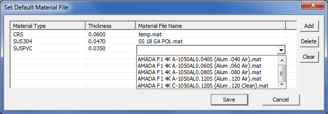
Set
Map for Material File Name
Double-click a column header to display the pull-down menu Note: If the machine in use doesn't have an associated material, then a Material File Name can't be added in this column. |
|
|
|
Option |
Description |
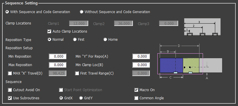
With Sequence and Code Generation |
This option enables the program to generate the sequence and NC code after the sheet is tooled and sequenced. This allows the user to review the contents of the NC file to ensure that the material will be processed correctly. This option is synchronized with the same option in the Machine Setting>Sheet Layout Info Panel>Sheet Wizard tab. |
Without Sequence and Code Generation |
This option will not allow the program to
generate the sequence and NC code after the sheet is tooled and
sequenced. |
Clamp Locations |
Clamps 1, 2 and 3 - When Auto Clamp Locations is unchecked, these fields become active. The user can then manually position the clamps according to the diagram at the right. This over-rides any other clamp settings. Auto Clamp Locations
|
Reposition Type |
Normal First Home
|
Reposition Setup |
Min Reposition Note: If Min Reposition <= 0.001, the system will use the Clamp Width to sequence the sheet. Min “Y” For Repo(A) This value is the minimum location that the hold-downs can be located in the Y direction in A. (See diagram to the right of the Reposition fields.) Max Reposition Min Clamp Loc(B) Max “X” Travel(D) First Travel Range (C) Generally, First Travel Range should be smaller than the regular travel zone. The system will check and compare with the punch tool travel zone/cutting travel zone and the Max “X” Travel, and take the smallest value to process. (See diagram to the right of the Reposition fields.)
|
Sequence
|
Cutout
Avoid On Start
Point Optimization Macro On Use Subroutines Grid X, Grid Y Common Angle |
|
|
|
Option |
Description |
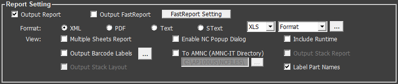
Output Report |
The user has the option of generating or not generating reports and their related files. By default the program will generate reports. To NOT generate reports uncheck the box (NC code generation remains enabled) . When this is done, the user may still make changes to the options in this section, but they will take effect in reports only after Output Report is enabled again. Generated reports are sent to the C:\AP100US\REPORTS
and NCFiles folders. |
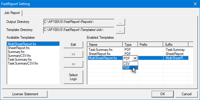
FastReport generates and outputs reports in multiple formats, supports various data sources and has built-in scripts for handling complex data. To open and configure FastReport click the FastReport Setting button. To enable FastReport to output customized reports for jobs in the Sheet Wizard, check ON the Output FastReport checkbox in the Report Setting section. Note: If Output FastReport is switched ON and the Output Report is switched OFF, selecting the View Reports button in Start Nesting will show the FastReport.
Generated reports are found in the C:\AP100US\FastReport\Reports folder. NC code should be generated before a report is produced. Output Directory and Template Directory
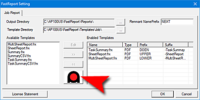
Remnant Name Prefix The Remnant name entered here is updated to the C:\AP100US\Parm folder - Setting.ini file. Available Templates Enabled Templates In the Type column, click in a cell to open the pull-down menu and choose CSV or PDF for the report output format. The Prefix cell can contain a prefix that the user enters, which will be attached to the beginning of the name. Cells in the Suffix column are edited in the same manner. Note: Edit Select Logo
License Statement Note: FastReport in the Sheet Wizard is NOT synchronized with the same option in AP100US.
|
|
Format |
XML PDF Text SText Format (None) See Machine Information>Sheet Layout Info for more info.
|
View
|
Multiple Sheets Report Uncheck the box and each sheet will have a separate report. Any report(s) will be viewable by clicking on the View Report button. Enable
NC Popup Dialog Include
RunTime Note: Run Time will not display in the interface or the report if there are problems with the material in use, such as no JKA file, insufficient quantity, etc. Be sure to check the Material! To
AMNC (AMNC-IT Directory) Note: An LI1 file is a schedule file that contains nesting results including the NC code. See AMNC-IT Controller for more info.w Output
Barcode Labels See Machine Information>Sheet Layout Info for more info. Output
Stack Report Output
Stack Layout Note: These two options are synchronized with the same options in Preferences>NC File. Label Part Names . Note: This option is NOT linked to "Label Part Names" in the Print Settings dialog.
|
|
Click on one of the buttons to open the various windows described below. In these windows the user can set the necessary parameters for the nesting, including machine info setting, sheet info setting, turret setting, cut direction setting, material setting, nesting parameters setting and preference setting. |
||
Option |
Description |
|
|
Click on the Preferences button to display the Preferences window. Here any system settings can be changed prior to nesting. See Preferences > Default Values for more information.
|
|
|
Click on the Material button to display the Lead In & Lead Out window. After the machine is loaded, the default material setting can be edited here. Note: When there is no machine loaded, this button is grayed out. See Material>Lead In & Lead Out for more information.
|
|
|
After a cutting or combo machine is loaded, the user can pre-define the cutting direction for the cutting sequence. Click the Sequence Direction graphic to toggle through the various sequence direction options and then enter a Path Width value. Note: When there is no machine loaded or the current loaded machine is a punch machine, this button is grayed out.
|
|
|
|
Shortest Path. The system will sequence the sheet using the shortest distance from the last pattern sequenced.
|
|
|
X-Axis. Use this option to sequence the sheet in the X direction before moving along the Y-axis.
|
|
|
Y-Axis. Use this option to sequence the sheet in the Y direction before moving along the X-axis.
|
|
|
Line-By-Line X. Use this option to sequence the sheet along the primary X-axis, return to the original starting edge, and then sequence the tool along the closest pattern off the primary axis from the last sequenced pattern.
|
|
|
Line-By-Line Y. Use this option to sequence the sheet along the primary Y-axis, return to the original starting edge, and then sequence the tool along the closest pattern off the primary axis from the last sequenced pattern.
|
|
Click on the Machine Setting icon to display the Machine Setting window. Machine related info for the Wizard, including Driver and JKA (or other JK... file) can be configured here. See Machine Setting>Sheet Layout Info for more info.
|
|
|
Click on the Sheet Information icon to display the Sheet Information window. This window displays sheet-related information, such as Material Type, sheet size and thickness. In this dialog box changes can also be made to the current sheet settings, such as material type, sheet size and thickness. The current machine inventory and material file can also be changed. If the machine is changed here, the corresponding machine name will display in the Sheet Wizard main window. See Sheet Information for more info.
|
|
|
To allow the user to easily make last-minute adjustments to TK unloader settings, click this button to open the TK Settings window.
|
|
|
After a Punch or Combo machine is loaded, click this button to open the Turret inventory. Adjust tool settings here, assign a tool to a certain station, add tool conditions, specify a pre-punch tool, scribe tool and so on. Basically, the system will load the default inventory of the current machine; however, if the user wants to change to another inventory, besides changing it in Sheet Info, he also could go to the “Tool Inventory” tab of this dialog, and load another inventory. Note: If there is no machine loaded, or the current loaded machine is a cutting machine, this button is disabled. See Turret Window for more information. |
|
|
|
|