Note: Options are driver-dependent; certain options shown here may or may not appear or be active depending upon the driver currently loaded.
TK Unloader Settings
When using the Multiple TK Unloading system, this version of the TK Info window displays when the Modules>TK Information Settings icon is selected.
This
page contains information about options unique to the TK Unloader.
For documentation on all other fields, see the PSR
Unloader Settings page.
See Part Conveyor Option, Microjoint Cutter for TK Unloader (MJC) and TK-L Part Remover Arm Implementation below.
Note: Options are driver-dependent;
certain options shown here may or may not appear or be active depending
upon the driver currently loaded.
Part
Conveyor option in Storage Table
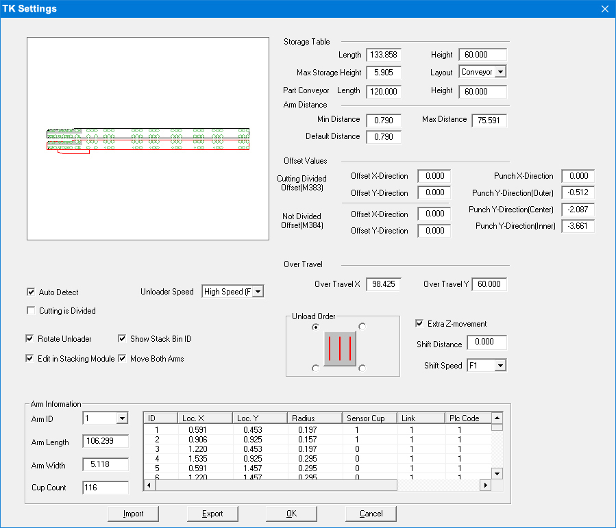
The Storage Table section now contains a Part
Conveyor option that
allows users to be able to visualize and configure part unloading to a
conveyor belt in the AP100US interface. This driver-dependent option is
for users equipped with an Amada EML machine with Part Conveyor
option.
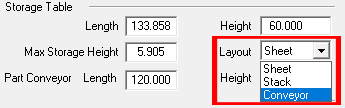
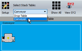
Enter the Part Conveyor Length and Height based on the actual dimensions of the Part Conveyor on the shop floor and then from the Layout pull-down menu select Conveyor. Selecting Conveyor instructs the system to bypass the drop table and place parts on the Part Conveyor. The values entered will affect the display of the Part Conveyor in the AP100US Work Area, and also affect the placement of the unloaded parts.
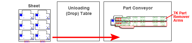
To unload parts to the Part Conveyor, select Auto Unload to unload all the parts on the sheet to the Conveyor. The system will auto-select the optimum placement of the parts based on the Length and Height X/Y values entered by the user in the TK Settings panel.
During unloading, the conveyor may be in motion and the parts will be spread out in a row as the conveyor belt moves. However, the operator may shut off the conveyor, in order to stack the parts normally. The Part Conveyor itself is controlled by the operator, not by settings in the CADCAM program.
The user may also manually unload parts to the Part Conveyor. Regardless of where the first part is placed, the system will automatically move it to the correct place. The user may unload one or more parts as needed, or begin by manually unloading the first part and then selecting Auto Unload, which will unload all other parts on the sheet, stacking them on top of the manually unloaded part.
Note: When editing part conveyor size in the TK/PSR Settings window, the user should save the current machine in the Machine Settings>Description panel to save these new values as the default.
Use in Part Stacking Module
The Part Conveyor option is also added to the Part Stacker module to allow
users to visualize part unloading to a conveyor belt in the Part Stacker
Module. Part stacking to a conveyor follows the same rules as stacking
to a drop (stacking) table. See Part Stacker
Module>Stack Table Menu for more info.
This option supports microjoint cutting and part unloading for machines that have a microjoint cutter on the Multiple TK Unloading system such as with the Amada Acies machine.
Note:
The correct Machine/Driver that supports this function must be loaded
for the Acies MJC Setting - ![]() - icon to become available
on the Modules>Unloading
menu. (Use specialized driver such as the AMADA LC2515C1AJ 49 STA AI MULTI-TK
V2014.mac.)
- icon to become available
on the Modules>Unloading
menu. (Use specialized driver such as the AMADA LC2515C1AJ 49 STA AI MULTI-TK
V2014.mac.)
How the Option Works
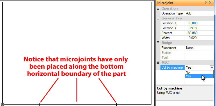
1) To begin with the user must place microjoints from the Sequence Features>Punch Features menu. Be sure to place microjoints ONLY along the bottom horizontal line boundary of the part. (If microjoints are placed along other boundaries, the program will show an error.) Amada recommends using a Bowtie tool at a size of 0.039 for the microjoint. For the lower-left microjoint, it's best to place it no less than 10 inches in from the edge to allow for the part remover arm.
The lower-left microjoint should be placed
no less than 10 inches in from the left edge
Once microjoints have been placed, they may be edited in the Microjoint panel as shown above. To enable the option, select Yes from the MJC/Cut by machine pull-down menu.
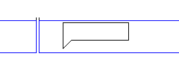
Notice the unique shape of the MJC microjoint
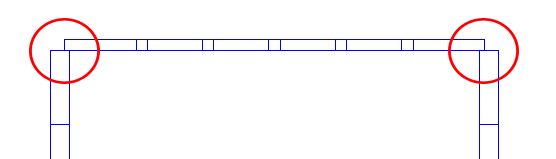
2) Tool the part normally. The user may choose to overcut the upper boundary to ensure a thorough cut (shown circled in red in the image below) by entering a negative Tab value. To learn how to make this overcut go to Tool Assign>Tabs.
3) As the microjoint cutter equipment is on the lower TK pickup arm, the user must assign the LOWER TK pickup arm to the part(s).
See Modules>Unloading for more info.
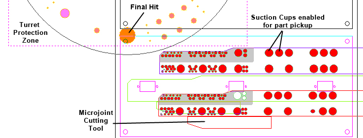
Graphic illustration of turret, PR arms & MJC tool on a sheet
The
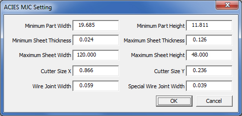
user may stay with default settings for this option, or click the ![]() icon to open the ACIES MJC Setting dialog.
icon to open the ACIES MJC Setting dialog.
Options here allow the user to set ranges that will specify certain parts for cutting with the MJC TK cutter, and those that will be bypassed.
Notes:
The MJC TK Cutter is compatible with certain other features (such as Notches) that are added to the bottom
boundary.
The Microjoint tool should be smaller
than the tool assigned to the part boundary, otherwise an error dialog
will display.
If even one Setting parameter is incorrect, the MJC microjoints will not
display on the part.
TK-L Part Remover Arm Implementation
This option includes a part pickup arm with two moveable side arms that may be dragged over a part or part group; this increases the "reach" of the part remover arm. Drag the arms using the cursor/crosshair to the desired place, and then right-click to finalize the position.
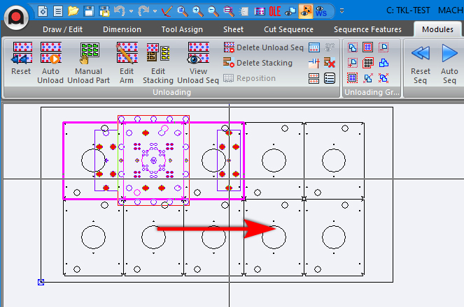
The right moveable arm is dragged to
the right
Notice the crosshair on the right arm
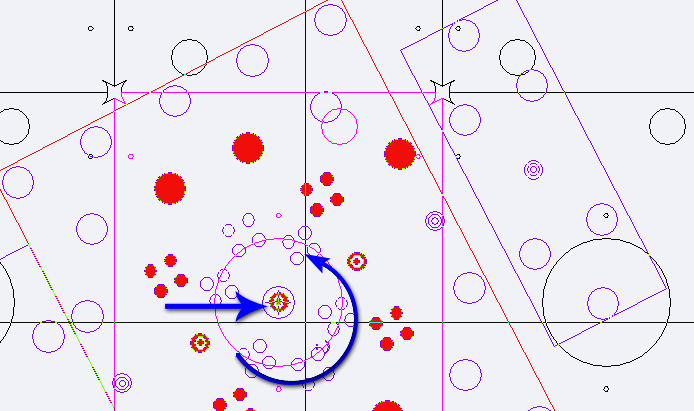
To rotate the arm, with the cursor/crosshair select the arm precisely at the center point (indicated by the blue arrow), hold the mouse button down and then drag in a circular motion.
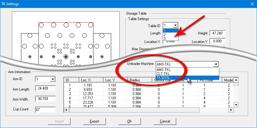
When TK is selected as an Unloader Machine, three storage tables are allowed.